Non-contact flexible controller and preparation method thereof
A non-contact, controller technology, used in instruments, electrical digital data processing, data processing input/output processes, etc., can solve problems such as low accuracy, and achieve low cost, low resistance, and good mechanical ductility. Effect
- Summary
- Abstract
- Description
- Claims
- Application Information
AI Technical Summary
Problems solved by technology
Method used
Image

Examples
Embodiment 1
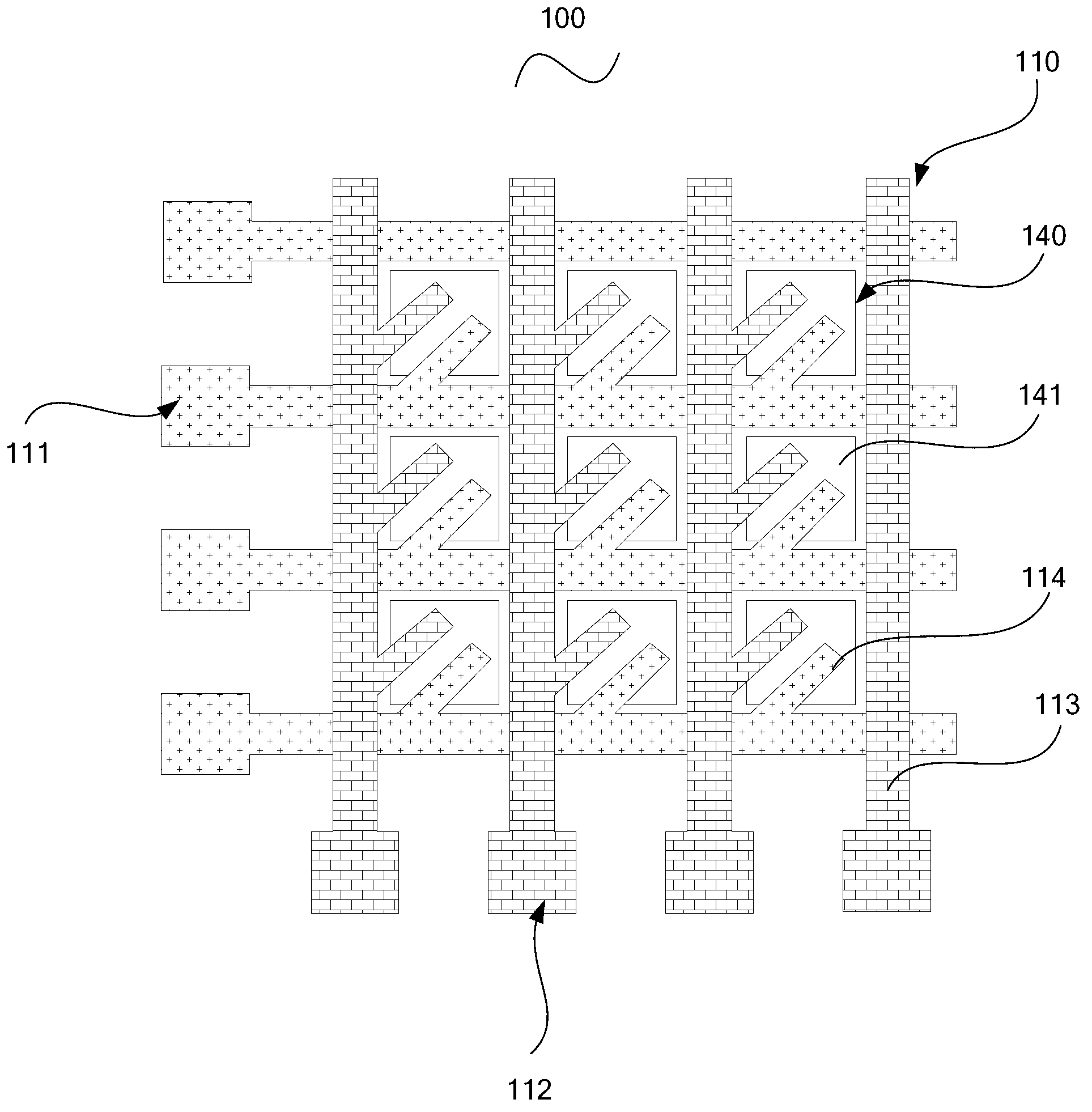
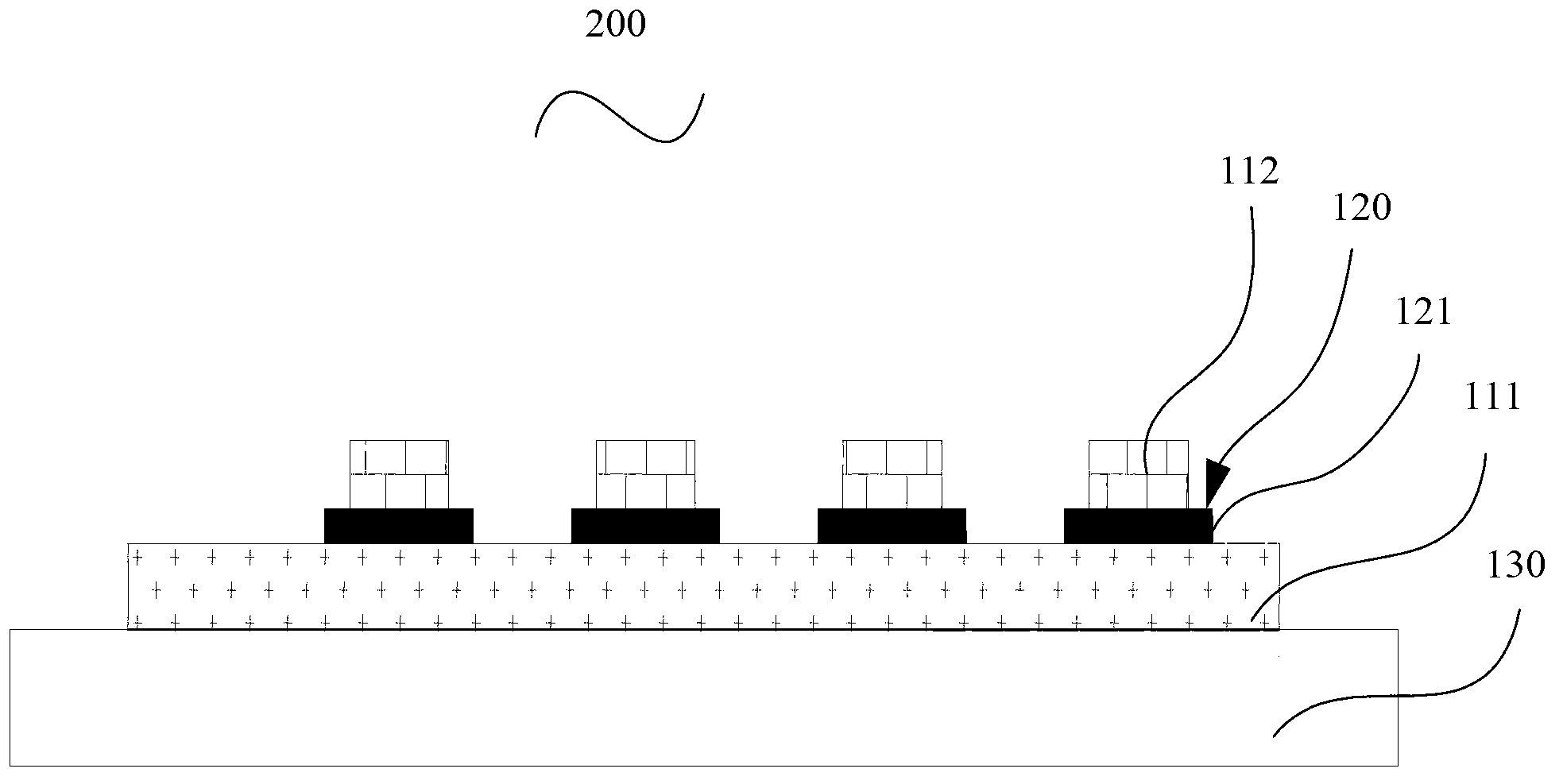
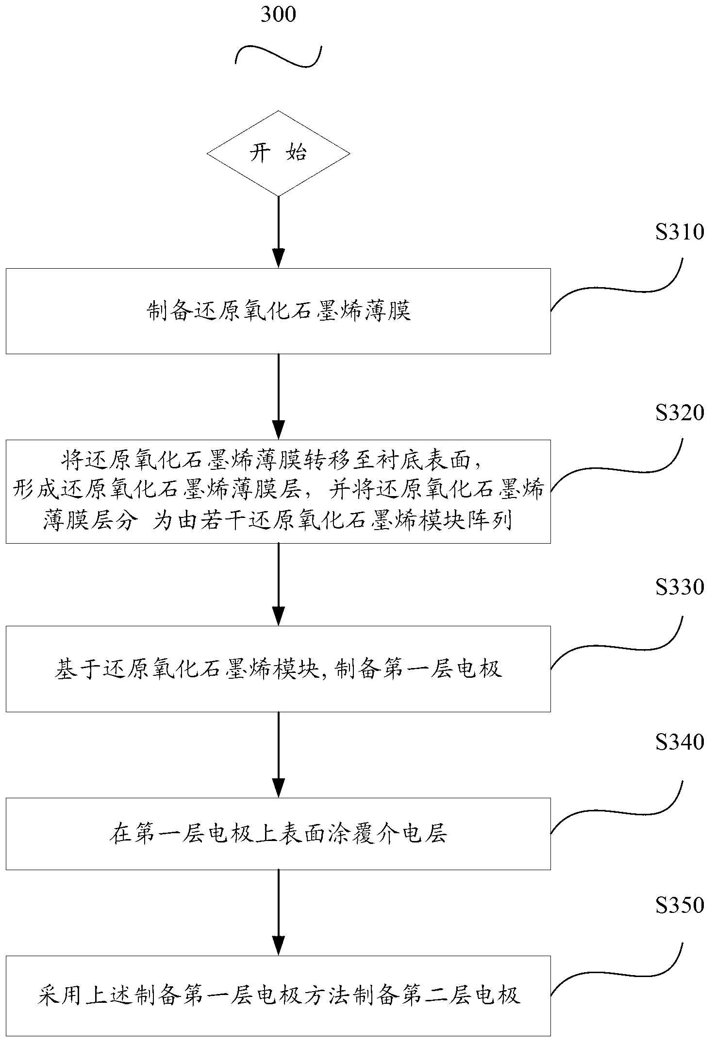
[0112] The reduced graphene oxide film is transferred to a polyethylene terephthalate (PET) substrate, and then the reduced graphene oxide film is cut into a size of 1.5×1.5mm by physical cutting under the cover of a cutting mask 2 100 reduced graphene oxide module arrays, the gap distance between each reduced graphene oxide module is 2.5mm, and then under the cover of another mask plate, vapor deposition is 46mm long and 0.5mm wide at the transverse gap of the reduced graphene oxide module array. mm, a Ni layer with a thickness of 20nm, and then evaporate an Au layer with a length of 46mm, a width of 0.5mm, and a thickness of 120nm on the Ni layer under the cover of the mask plate under the same conditions. The Ni layer and the Au layer together constitute the first layer of electrodes. Then, under the cover of the cutting mask, a layer of PDMS with a length of 0.6 mm, a width of 0.6 mm (slightly wider than the electrode), and a thickness of about 500 μm is evenly coated on th...
Embodiment 2
[0116] The reduced graphene oxide film is transferred to a polyethylene terephthalate (PET) substrate, and then the reduced graphene oxide film is cut into a size of 1.5×1.5mm by physical cutting under the cover of a cutting mask 2 100 reduced graphene oxide module arrays, the gap distance between each reduced graphene oxide module is 2.5mm, and then under the cover of another mask plate, vapor deposition is 46mm long and 0.5mm wide at the transverse gap of the reduced graphene oxide module array. mm, 20nm thick Cd layer, and then vapor-deposit a 46mm long, 0.5mm wide, 120nm thick Au layer on the Cd layer under the cover of the mask under the same conditions, the Cd layer and the Au layer together constitute the first layer of electrodes, Then, under the cover of the cutting mask, a layer of PDMS with a length of 0.6 mm, a width of 0.6 mm (slightly wider than the electrode), and a thickness of about 500 μm is evenly coated on the vertical intersection of the horizontal gap and ...
Embodiment 3
[0118] The reduced graphene oxide film is transferred to a polyethylene terephthalate (PET) substrate, and then the reduced graphene oxide film is cut into a size of 1.5×1.5mm by physical cutting under the cover of a cutting mask 2 100 reduced graphene oxide module arrays, the gap distance between each reduced graphene oxide module is 2.5mm, and then under the cover of another mask plate, vapor deposition is 46mm long and 0.5mm wide at the transverse gap of the reduced graphene oxide module array. mm, a Ni layer with a thickness of 20nm, and then evaporate an Ag layer with a length of 46mm, a width of 0.5mm, and a thickness of 120nm on the Ni layer under the cover of the mask plate under the same conditions. The Ni layer and the Ag layer together constitute the first layer of electrodes. Then, under the cover of the cutting mask, a layer of PDMS with a length of 0.6 mm, a width of 0.6 mm (slightly wider than the electrode), and a thickness of about 500 μm is evenly coated on th...
PUM
 Abstract
Description
Claims
Application Information
 - R&D
- Intellectual Property
- Life Sciences
- Materials
- Tech Scout
- Unparalleled Data Quality
- Higher Quality Content
- 60% Fewer Hallucinations
Browse by: Latest US Patents, China's latest patents, Technical Efficacy Thesaurus, Application Domain, Technology Topic, Popular Technical Reports.
© 2025 PatSnap. All rights reserved.Legal|Privacy policy|Modern Slavery Act Transparency Statement|Sitemap|About US| Contact US: help@patsnap.com