Monitoring and controlling system based on optical communication

A monitoring control and optical communication technology, applied in signal transmission systems, non-electrical signal transmission systems, comprehensive factory control, etc., can solve the problems of wasting labor, adjusting temperature and humidity regulators, wasting energy, etc. Effect

Active Publication Date: 2013-09-11
KUANG CHI INTELLIGENT PHOTONIC TECH
View PDF4 Cites 18 Cited by
  • Summary
  • Abstract
  • Description
  • Claims
  • Application Information

AI Technical Summary

Problems solved by technology

[0003] Although temperature regulators and humidity regulators are widely used in various fields, however, because the existing monitoring system cannot timely adjust the temperature and humidity regulators according to the environment, a lot of energy is wasted, especially in industrial and agricultural production. Waste of energy and waste of labor
For example, in our daily life, the air conditioner is still on after the temperature reaches the set temperature. Although the energy consumption is reduced, there is still wasted energy. The same problem exists in the humidifier.

Method used


Image

  • Monitoring and controlling system based on optical communication
  • Monitoring and controlling system based on optical communication
  • Monitoring and controlling system based on optical communication

Examples


Embodiment Construction

[0020] The present invention will be further described below in conjunction with the drawings and specific embodiments:

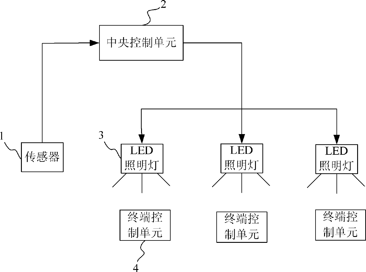
[0021] See figure 1 The optical communication-based monitoring and control system of the present invention includes a sensor 1, a central control unit 2, an optical signal transmitting unit 3, and a terminal control unit 4. The sensor 1 is used to detect the measured and transmit corresponding information to the measured Mentioned central control unit 2. The measured may be one or more of temperature, humidity, illuminance, pH, pressure, flow, liquid level, differential pressure, ultrasound, and weight. In this embodiment, the sensor 1 is smart dust.

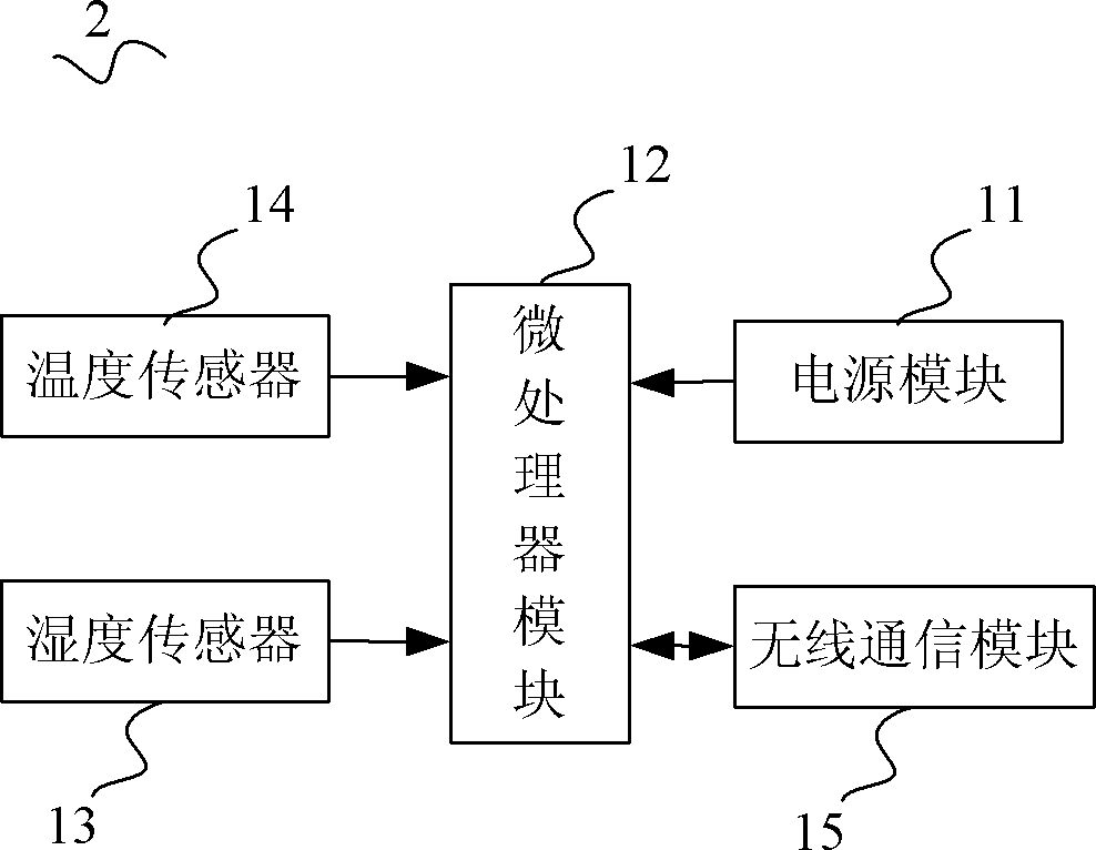
[0022] See figure 2 , Smart dust refers to an ultra-miniature sensor with computer functions1, and the existing smart dust has a volume of about 5mm 3 , It can detect many surrounding environmental parameters, collect large amounts of data, perform appropriate calculations, and then use two-way wireless communic...


PUM


Abstract

The invention relates to a monitoring and controlling system based on optical communication. The monitoring and controlling system comprises a sensor, a central control unit, an optical signal transmission unit and a terminal control unit, wherein the sensor is used for detecting measurand and transmitting corresponding information of the measurand to the central control unit; the central control unit is used for transmitting a control instruction to the optical signal transmission unit according to the information of the measurand; the optical signal transmission unit is used for transmitting out the control instruction in a form of an optical signal; the terminal control unit is used for receiving the optical signal and controlling terminal equipment according to the optical signal. According to the monitoring and controlling system based on optical communication disclosed by the invention, the detection control on the measurand is realized, so that a spectrum resource does not need to be applied for, no electromagnetic interferences exists, and the resource utilization efficiency can be improved. The monitoring and controlling system can be used for monitoring and controlling the measurand such as temperatures, humidity, illumination intensity, pH (Potential of Hydrogen) values, pressure, flows, liquid levels, differential pressure and ultrasonic waves.

Description

Technical field [0001] The invention relates to a monitoring and control system, in particular to a monitoring and control system based on optical communication. Background technique [0002] In warehouse management, manufacturing, breeding and nursing, meteorological observation, scientific research, and daily life, requirements for temperature, humidity, and light intensity are common. For example, in the management of archives, there are usually the following requirements: Archives (including film library) The temperature of the tape library should be controlled at 14~24℃, the daily change range of the warehouse with equipment should not exceed ±2℃; the relative humidity should be controlled at 45%~60%, and the daily change range of the warehouse with equipment should not exceed ±5% . With the rapid development of science and technology and the improvement of people's overall environmental awareness, people will also demand a balance between the comfort of the living environm...

Claims


Application Information

Patent Timeline
Patent Type & Authority Applications(China)
IPC IPC(8): G08C23/04G05B19/418
Inventor 刘若鹏栾琳刘敏钟果
Owner KUANG CHI INTELLIGENT PHOTONIC TECH
Why Eureka
Try Eureka