Residual heat removal system of nuclear reactor

A waste heat removal system and nuclear reactor technology, applied in reactors, nuclear engineering, nuclear power generation, etc., can solve problems such as complex systems, many intermediate processes, and increased probability of system failure, and achieve simple systems, fewer intermediate processes, and high reliability Effect

Inactive Publication Date: 2013-09-11
SHANGHAI NUCLEAR ENG RES & DESIGN INST CO LTD
View PDF5 Cites 7 Cited by
  • Summary
  • Abstract
  • Description
  • Claims
  • Application Information

AI Technical Summary

Problems solved by technology

The system takes away the decay heat from the secondary side of the steam generator of the nuclear power plant system, and the heat taken away is transferred to the steam condensate tank in the containment through the passive waste heat discharge heat exchanger on the secondary side, and the temperature and pressure reduction function of the containment It is realized by spraying inside the containment, that is to say, it is similar to the deficiency of Document 1, that is, it only brings the heat of the reactor core into the containment, and the design of the reactor requires that the heat must be transferred to the final heat sink , so another set of equipment is needed to bring the heat to the final heat sink outside the containment, the system is complex, there are many intermediate processes, and the probability of system failure will inevitably increase; The water tank device, so the water volume in the system is small, and it is difficult to ensure the reliable operation of the system only by relying on the initial water volume of the steam generator;

Method used


Image

  • Residual heat removal system of nuclear reactor
  • Residual heat removal system of nuclear reactor

Examples


Embodiment 1

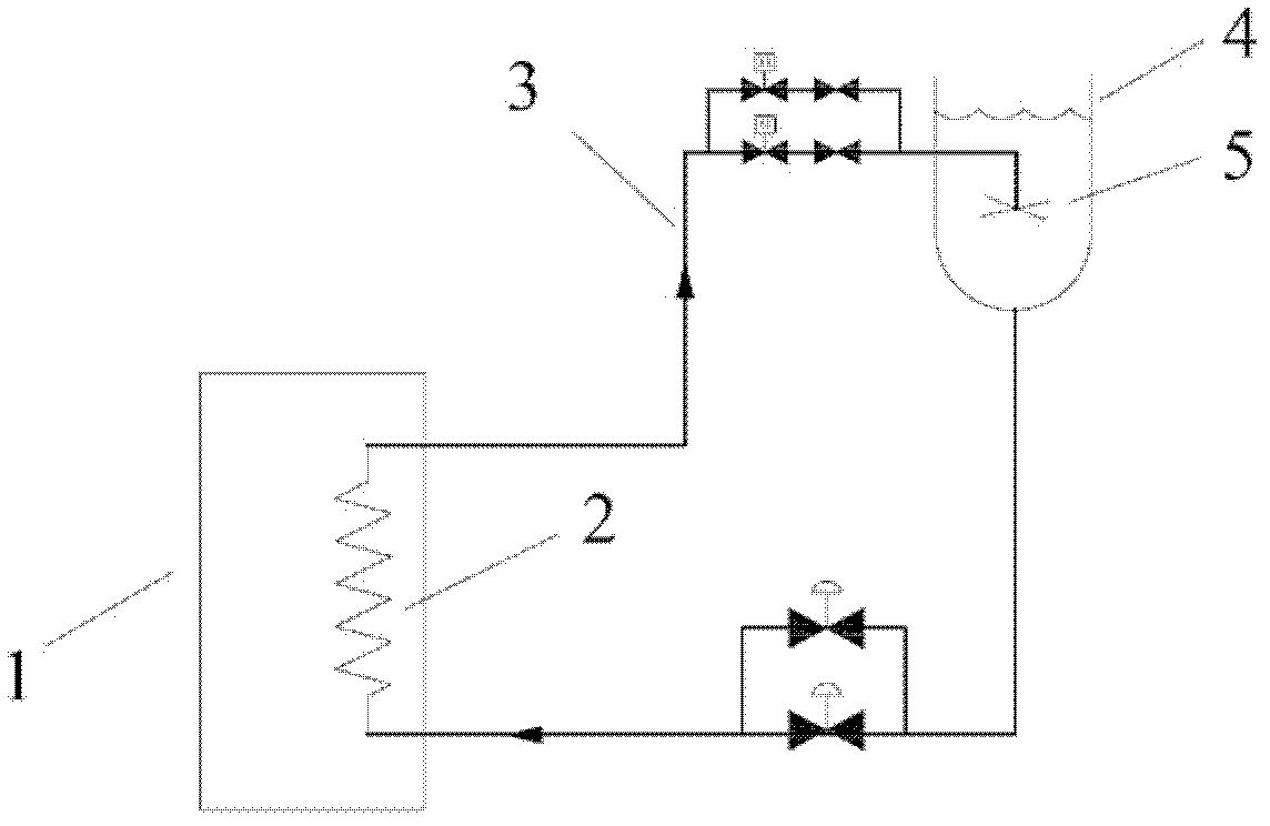
[0017] figure 1 As shown, the waste heat removal system of the nuclear reactor includes the main reactor coolant 1, the waste heat heat exchanger 2, the passive feed water tank 4, and the sprinkler 5. The reactor main coolant 1 forms a loop with the reactor core to take away core heat, and the reactor main coolant 1 contacts with the waste heat exchanger 2 for heat exchange. The waste heat heat exchanger 2, the passive water supply tank 4, and the sprinkler 5 form a flow circuit of heat exchange working medium through pipes, and the working medium in the passive water supply tank 4 and the waste heat discharge system connected with it is water, which can also be replaced by other Feasible working medium.

[0018] The waste heat exchanger 2 is connected to the sprinkler 5 through a pipeline, and the sprinkler 5 is submerged in the passive water feed tank 4 .

[0019] Valves are set on the pipeline 3 of the waste heat discharge system, and the valves can be combined with diffe...

Embodiment 2

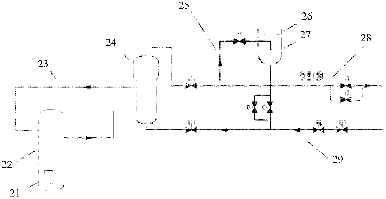
[0026] Such as figure 2 As shown, in Embodiment 2, the steam generator 24 of the reactor is used as the waste heat exchanger, and the inlet and outlet of the waste heat exchanger 24 are respectively connected to the main feedwater pipeline 9 and the main steam pipeline 28 of the reactor, and the main steam pipeline is used to 28 and the part of the main water supply pipeline 29 close to the steam generator are used as a part of the waste heat removal system.

[0027] After a reactor accident, the waste heat of the core can be discharged through the waste heat removal system. The specific process is as follows:

[0028] When the reactor shuts down due to an accident, the isolation valve between the main steam pipeline 28 and the steam turbine is closed to isolate the main steam pipeline so that the main steam pipeline 28 only functions as a part of the waste heat discharge system. Also the main water supply isolation valve is closed to isolate the main water supply pipeline 2...


PUM


Abstract

The invention aims to provide a residual heat removal system of a nuclear reactor, which is used for enhancing the reliability of residual heat removal of the nuclear reactor. The residual heat removal system of the nuclear reactor comprises a main reactor cooling agent, a residual heat exchanger, a passive water feeding tank and a spraying device; a work medium flows into an inlet of the residual heat exchanger from the passive water feeding tank, and is used for absorbing heat of the main reactor cooling agent, which is transmitted by the residual heat exchanger; then, the work medium flows to the spraying device from an outlet of the residual heat exchanger and then is sprayed into the passive water feeding tank from the spraying device; the passive water feeding tank is higher than the residual heat exchanger.

Description

technical field [0001] The invention relates to a safety protection system of a nuclear reactor, in particular to a waste heat discharge system of a nuclear reactor. Background technique [0002] The waste heat removal system is an important measure for reactor safety protection. In the event of an accident, since the reactor continues to generate decay heat after shutdown, the decay heat needs to be discharged to avoid heat accumulation in the reactor and damage to the core and pressure boundary due to excessive temperature and pressure. [0003] Chinese utility model patent 201020227239.X (document 1) discloses a safety system for ensuring the safety of nuclear power plants, which relates to a safety system for ensuring the safety of nuclear power plants. The equipment and space in the containment are sprayed and cooled, which can take away the heat in the containment, reduce the pressure in the containment, and prevent the overpressure of the containment. Furthermore, h...

Claims


Application Information

Patent Timeline
Patent Type & Authority Applications(China)
IPC IPC(8): G21C15/18
CPCY02E30/30
Inventor 司胜义林千廖亮申屠军
Owner SHANGHAI NUCLEAR ENG RES & DESIGN INST CO LTD
Why Eureka
Try Eureka