
Device for preparing nanofibers by differential split-flow centrifugal spinning method

A centrifugal spinning and nanofiber technology, applied in fiber processing, textiles and papermaking, filament/thread forming, etc., can solve problems such as energy consumption and safety, uneven fiber thickness, and increased rotation speed

Inactive Publication Date: 2013-09-18
QINGDAO ZHONG KE HAO TAI NEW MATERIAL SCI & TECH +1
View PDF14 Cites 28 Cited by
  • Summary
  • Abstract
  • Description
  • Claims
  • Application Information

AI Technical Summary

Problems solved by technology

[0005] Nevertheless, the nozzles proposed above realize the quantification and refinement of spinning through multiple micro-holes. The horizontal disc type has the problems of uneven fiber thickness and thick fluid layer. To further increase the output and obtain finer fibers, it is necessary to Through the cooperation of more and finer micro-hole machining and faster rotation speed, the complexity of processing and the energy consumption and safety problems caused by the increase of rotation speed

Method used


Image

  • Device for preparing nanofibers by differential split-flow centrifugal spinning method
  • Device for preparing nanofibers by differential split-flow centrifugal spinning method
  • Device for preparing nanofibers by differential split-flow centrifugal spinning method

Examples


Embodiment Construction

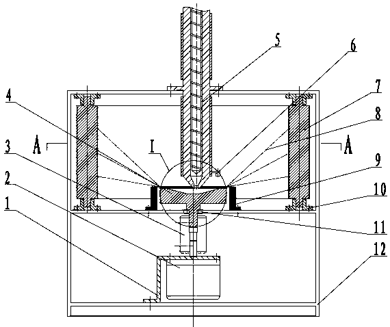
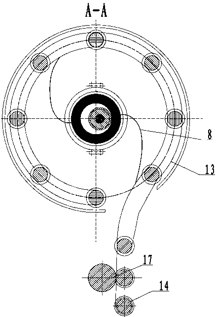
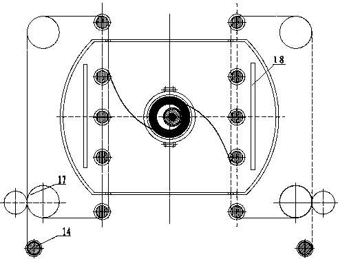
[0023] A kind of device of the present invention prepares nanofiber by differential flow centrifugal spinning method, such as figure 1As shown, it mainly includes motor bracket 1, high-speed motor 2, coupling 3, rotating body 4, continuous feeding device 5, infrared temperature sensor 6, conveyor belt roller group 7, electromagnetic heater 9, roller bearing housing 10, rotating Body bearing 11, spinning box 12, transport cord 13, rolling device 17, winding device 14, wherein the motor bracket 1 is fixed on the lower part of the spinning box 12 to fix the high-speed motor 2, and the high-speed motor 2 passes through the coupling 3 and the rotating body bearing 11 drive the rotating body 3 to rotate at high speed, the continuous feeding device 5 is fixed on the top of the spinning box 12, the discharge port is placed on the upper end of the rotating body 4 in an eccentric manner and keeps a small distance, and the infrared temperature sensor 6 is fixed Connected to the continuou...


PUM


Abstract

The invention discloses a device for preparing nanofibers by a differential split-flow centrifugal spinning method. The device mainly comprises a motor support, a high-speed motor, a coupling, a rotator, a continuous feed device, an infrared temperature sensor, a conveyer belt roller set, an electromagnetic heater, a roller bearing block, a rotator bearing, a spinning manifold, conveying cord fabric, a rolling device and a take-up device. The motor support is fixedly arranged on the bottom bin of the spinning manifold and is used for fixing the high-speed motor; the rotator is driven to rotate at a high speed by the high-speed motor through the coupling and the rotator bearing; the continuous feed device is fixedly arranged at the top end of the spinning manifold; a discharge hole of the continuous feed device is arranged at the upper end of the rotator in an eccentric way, and a small interval is kept between the discharge hole and the upper end of the rotator. By combining a fluid differential structure and a reinforced fluid reduced conical surface, the control on the reduced degrees and centrifugal forces of fluids with different viscosity is realized, and meanwhile, a simple and efficient solution is provided to batch nanofiber preparation of solution or melt by the continuous feed device, an indirect heating device and the continuous take-up device.

Description

technical field [0001] The invention relates to a device for preparing nanofibers by using a differential split flow centrifugal spinning method, which belongs to the field of spinning and forming. Background technique [0002] With the rapid development of nanotechnology, the demand for devices and processes for preparing nanofibers in batches is becoming more and more urgent, and the application research is becoming more and more prosperous. Researchers have proposed several methods and processes for preparing nanofibers, such as template method, self-assembly method, phase separation method, and electrospinning method. Among them, electrospinning method has attracted much attention due to its simple equipment and preparation process, and has gradually developed. Batch equipment has been released, but the efficiency and fiber strength of the solution electrospinning method still need to be improved. The batch technology of melt electrospinning is still in the stage of deve...

Claims


Application Information

Patent Timeline
IPC IPC(8): D01D13/00D01D5/18
Inventor 杨卫民谈述战李好义王德禧吴昌政于水钟祥烽刘毅陈宏波周厚强谢同维丁玉梅
Owner QINGDAO ZHONG KE HAO TAI NEW MATERIAL SCI & TECH
Learn More