
Hydraulic Wax Removal Device for Rodless Pump Oil Production System

A technology of oil production system and rodless pump, which is applied in the direction of cleaning equipment, earthwork drilling, wellbore/well parts, etc. It can solve the problems of accelerated wax deposition in polymer flooding electric pump wells, increased labor intensity of workers, and limited weight of weighted rods, etc. problem, achieve the effect of promoting the progress of oil and gas field development technology, the outer diameter of wax removal is flexible and variable, and the labor intensity is low

Inactive Publication Date: 2015-07-29
NORTHEAST GASOLINEEUM UNIV
View PDF8 Cites 0 Cited by
  • Summary
  • Abstract
  • Description
  • Claims
  • Application Information

AI Technical Summary

Problems solved by technology

However, since the outer diameter of the wax removal tool is fixed, and the height of the lubricator is limited, the weight of the weighting rod is limited. In the case of severe wax deposition, it is difficult for the wax removal tool to be lowered into the well, and the normal wax removal process has evolved into a practical In the process of wax tapping, the steel wire needs to be manually lifted and released repeatedly, and the wax is removed under the action of the downward impact force generated by the wax scraper; in addition, taking Daqing Oilfield as an example, with the adoption of the polymer injection flooding method, the polymer The speed of wax deposition in electric drive pump wells is obviously accelerated, the precipitated wax has high viscoelasticity, the cycle of wax removal is shortened, and the difficulty of wax removal is increased, which causes the labor intensity of workers to increase significantly

Method used


Image

  • Hydraulic Wax Removal Device for Rodless Pump Oil Production System
  • Hydraulic Wax Removal Device for Rodless Pump Oil Production System
  • Hydraulic Wax Removal Device for Rodless Pump Oil Production System

Examples


Embodiment Construction

[0019] The present invention will be further explained below in conjunction with the drawings:

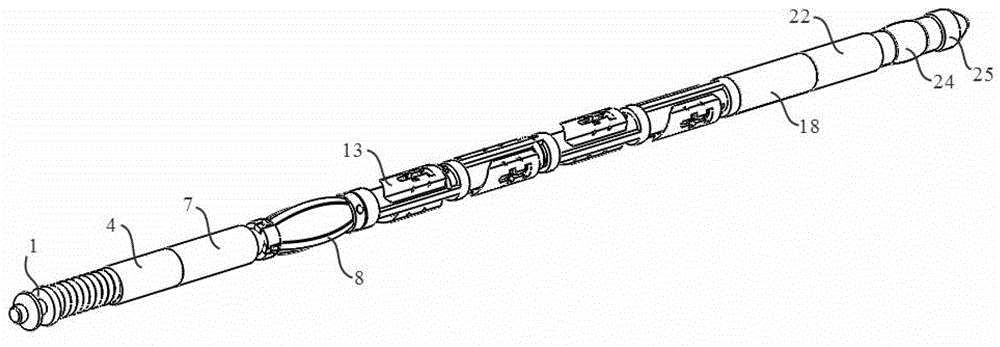
[0020] by figure 1 As shown, the hydraulic wax removal device of the rodless pump oil recovery system is divided into an inner and an outer two-layer structure. The outer layer is an outer sleeve unit, a scraper unit and a centralizing unit, and the inner layer is a central rod unit.

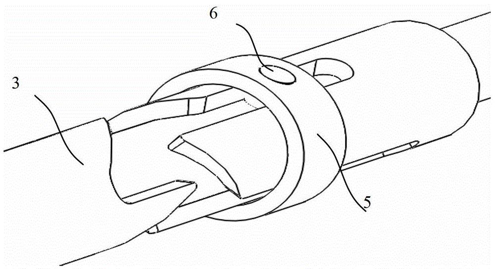
[0021] Wherein, the outer sleeve unit is formed by connecting No. 1 outer sleeve 4, No. 2 outer sleeve 7, No. 3 outer sleeve 12, inner cone sleeve 18, and No. 4 outer sleeve 22. A slip ring 5 is fixed between the outer sleeves 7. The structure diagram of the slip ring is as follows image 3 As shown, after being fixed, the slip ring 5 can rotate relative to the outer sleeve unit, but its axial direction does not move relative to the outer sleeve unit; the slip ring 5 is provided with a pin hole and a slip ring pin 6 is built in.

[0022] The scraper unit is as figure 1 , figure 2 , Figure 5 , Image 6 , ...


PUM


Abstract

The invention discloses a fluid power paraffin removal device of a rodless pump oil recovery system, and aims to provide an efficient paraffin removal device which is driven by utilizing the fluid power generated by the lifting of liquid flow in a pipe column, so that removing paraffin deposit on the wall of an oil pipe wall of the rodless pump oil recovery system is realized. The device is characterized in that the outer layer comprises an outer sleeve pipe unit, a scraper unit and a rubber barrel; the inner layer is a center rod unit; the scraper unit adopts a four-connecting-rod structure and is provided with a limiting stopper; direction-alternating and diameter-varied control structure for affecting the scraper unit and a mechanism for locking the rubber barrel are arranged on the center rod unit; the rubber barrel is used for changing the annular overflow area formed by the paraffin removal device in the oil pipe and controlling the fluid power born by the paraffin removal device, so that the rising and falling of the paraffin removal device are realized; through the relative position of the centre rod and the limiting stopper, the paraffin removal outer diameter opened by the scraper is controlled, so that gradual paraffin removal performed step by step is realized. The paraffin removal device has the advantages that the additional power is not required; the gradual paraffin removal performed step by step can be realized; the paraffin removal diameter is flexile and controllable; the labor intensity of workers is reduced; the working efficiency of paraffin removal is improved.

Description

Technical field [0001] The invention relates to a downhole tool applied in the field of petroleum and natural gas engineering, which can be used for removing wax on the inner wall of the oil pipe of a rodless pump oil production system. Background technique [0002] More than 80% of the crude oil produced in my country is waxy crude oil. Wax deposition is a thorny problem that has plagued the extraction of waxy crude oil for a long time. The cost of wax control and wax removal caused by wax deposition is also high. The main components of petroleum are hydrocarbons of various components, in which a certain amount of paraffin is dissolved. During the mining process, with the decrease of temperature and pressure and the precipitation of gas, the ability of crude oil to dissolve wax begins to decrease. The paraffin is precipitated as crystals, after agglomeration, and finally deposited on the solid surface such as the pipe wall. Mechanical wax removal is a commonly used wax removal...

Claims


Application Information

Patent Timeline
Patent Type & Authority Patents(China)
IPC IPC(8): E21B37/00E21B37/02
Inventor 王尊策张井龙吕凤霞李森徐艳温后珍
Owner NORTHEAST GASOLINEEUM UNIV
Learn More