
Waste heat recycle device for automobile cooling water

A waste heat recovery and cooling water technology, which is applied in liquid cooling, engine cooling, heat storage equipment, etc., can solve the problems of discontinuous waste heat, large total amount, instability, etc., and achieves simple structure, high temperature and easy production Effect

Inactive Publication Date: 2013-09-18
高志男
View PDF6 Cites 7 Cited by
  • Summary
  • Abstract
  • Description
  • Claims
  • Application Information

AI Technical Summary

Problems solved by technology

[0002] When the car is running, the cooling water is mainly used to reduce the body temperature of the engine. After the temperature of the cooling water rises, it goes to the water tank (that is, the water cooler) to cool down. Generally, the temperature of the cooling water or antifreeze can be as high as 80°C or more. Then enter the engine water jacket, and run repeatedly in this way. When the water passes through the water tank to cool down, the heat released is the so-called waste heat. Fundamentally speaking, this waste heat also comes from fuel consumption, and the total amount is not small. In view of the running time of the car Special and specific, resulting in the waste heat of cooling water being discontinuous, unstable and uncertain to a large extent, so far there is no waste heat recovery and utilization technology for automobile cooling water.

Method used


Image

  • Waste heat recycle device for automobile cooling water
  • Waste heat recycle device for automobile cooling water

Examples


Embodiment approach

[0013] Further detailed description in conjunction with the accompanying drawings; the arrows in the figure show the direction of fluid medium flow;

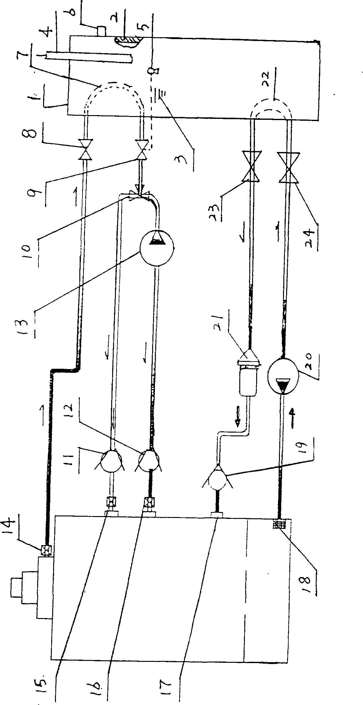
[0014] Such as figure 1 As shown: the waste heat recovery and utilization device for automobile cooling water has a heat storage and heat exchanger 1 with external heat preservation, heat transfer of heat-conducting working fluid, circulation pipeline and control system, and the specific structure of the heat storage and heat exchanger 1 is , has a shell 2, which is filled with a phase-change heat storage material 3 for storing heat and supplying heat to the outside, and is equipped with a temperature sensor 5 with an interlocking mechanism, and a heat exchange unit is also installed in it, and each heat exchange The units have inlets and outlets connected to the shell 2 respectively; the heat-conducting working medium in each heat exchange unit can circulate in the corresponding heat exchange unit through its corresponding inle...


PUM


Abstract

The invention relates to a waste heat recycle device for automobile cooling water and belongs to the field of waste heat recycle. Waste heat of the cooling water is recovered for low-temperature start of an automobile; the waste heat recycle device is provided with a heat storage and exchange device (1) internally equipped with a phase change heat storage material (3); the waste heat recycle device is internally provided with independent heat exchange units for transmitting and circulating heat outside with different heat-conducting working media and different circulation pipelines to heat an object; water serves as the heat-conducting working medium; the waste heat can be transmitted into the heat storage and exchange device (1) through the corresponding heat exchange units, and recovered and stored in the phase change heat storage material (3); the heat can also be transmitted outside to preheat the cooling water for the low-temperature start of an engine; in addition, preheated machine oil can be pumped into a main oil gallery of the engine first through the circulation pipeline of the heat transmission working medium, namely the machine oil, enters friction pairs to establish oil pressure, and can greatly reduce the friction during the low-temperature start of the engine; and the waste heat recycle device is energy-saving, environment-friendly, simple in structure, easy to implement and convenient to mount and use, does not influence the original automobile design, facilitates standard and industrial production, and is applicable to various motor vehicles.

Description

technical field [0001] The invention belongs to the technical field of waste heat recovery and utilization, and relates to a waste heat recovery device for automobile cooling water. Background technique [0002] When the car is running, the cooling water is mainly used to reduce the body temperature of the engine. After the temperature of the cooling water rises, it goes to the water tank (that is, the water cooler) to cool down. Generally, the temperature of the cooling water or antifreeze can be as high as 80°C or more. Then enter the engine water jacket, and run repeatedly in this way. When the water passes through the water tank to cool down, the heat released is the so-called waste heat. Fundamentally speaking, this waste heat also comes from fuel consumption, and the total amount is not small. In view of the running time of the car Particularity and specificity lead to discontinuous, unstable and uncertain waste heat of cooling water to a large extent. So far, no waste...

Claims


Application Information

Patent Timeline
Patent Type & Authority Applications(China)
IPC IPC(8): F02G5/00F28D20/00F01P3/20F01M5/02F02N19/10
CPCY02E60/14Y02T10/12
Inventor 高志男
Owner 高志男
Learn More