Heat accumulative gas burner

A gas burner, regenerative technology, applied in the direction of burner, gas fuel burner, combustion method, etc., can solve the problems of frequent ignition, poor performance, deflagration safety hazards, etc., to achieve sufficient combustion, convenient ignition, thermal efficiency high effect

Active Publication Date: 2013-09-18
JIANGSU TENGTIAN IND FURNACE
View PDF3 Cites 6 Cited by
  • Summary
  • Abstract
  • Description
  • Claims
  • Application Information

AI Technical Summary

Problems solved by technology

However, the two burners operate alternately, and frequent ignition has the following problems. The biggest problem is that there is a high configuration requirement for the ignition device. If a certain ignition error fails to ignite the gas in time, the accumulated high-concentration gas will easily cause deflagration. There is a major safety hazard in the deflagration in the furnace
Another problem is that the remaining gas in the burner will be discharged together with

Method used


Image

  • Heat accumulative gas burner
  • Heat accumulative gas burner
  • Heat accumulative gas burner

Examples


Embodiment 1

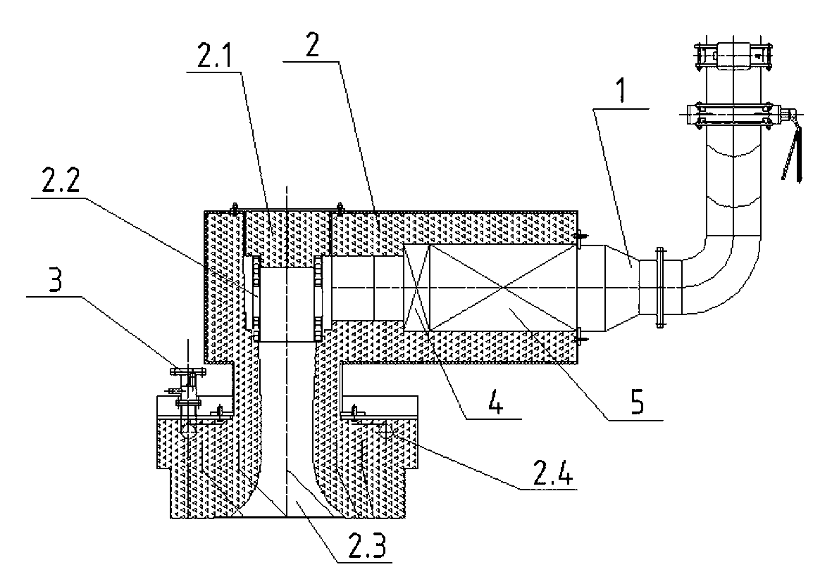
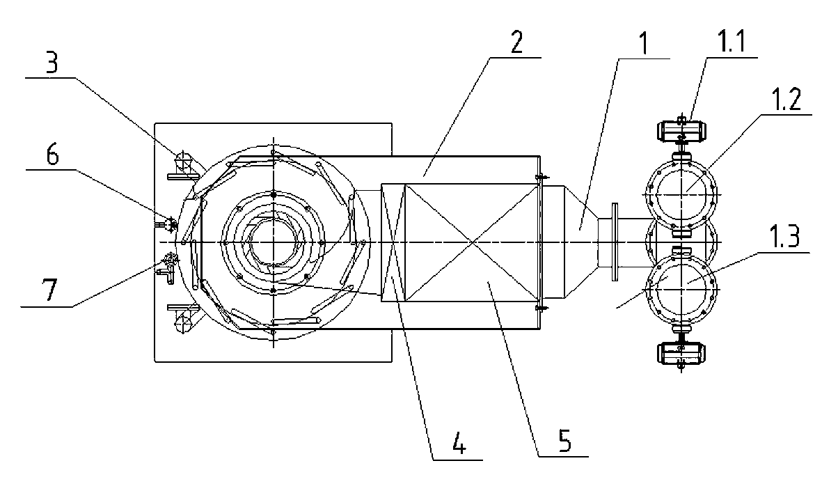
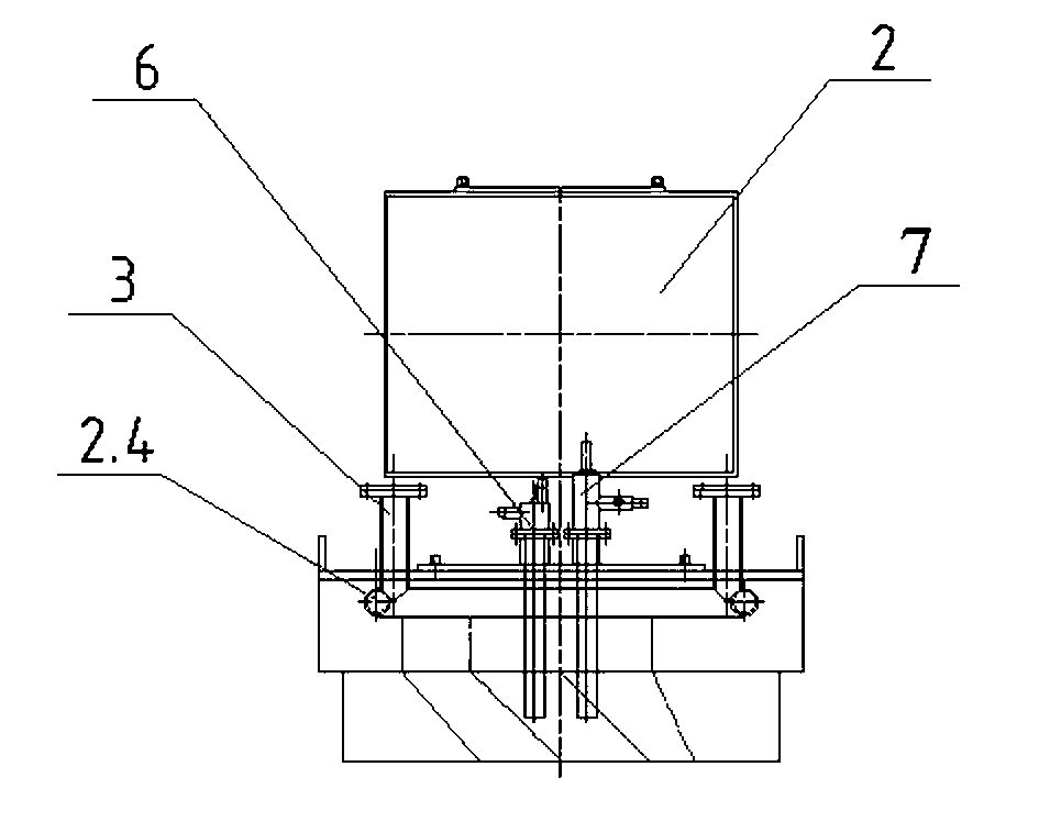
[0021] figure 1 The regenerative gas burner shown includes an air distribution device 1 , a nozzle 2 , a gas control assembly 3 , a block brick 4 , a heat storage body 5 , an ignition device 6 and a fire retention device 7 . The air distribution device 1 is a channel for introducing combustion-supporting air and exhausting exhaust gas. The channel is a three-way pipe fitting. The main pipe end is a rectangular pipe that is directly sealed and connected to the right end of the nozzle 2. The other pipe end is provided with two fork pipes. The forked pipe on one side is the air inlet pipe 1.2, and the other forked pipe arranged side by side is the smoke exhaust pipe 1.3. In order to control the medium flow and operating state in the fork pipe, the air inlet pipe 1.2 is equipped with a pulse device 1.1, and the smoke exhaust pipe 1.3 is equipped with a pulse device 1.1 and an air smoke proportional valve. The nozzle 2 is the core component. The present invention builds a cyclone ...

Embodiment 2

[0025] The gas volume of this embodiment is 175m 3 / h, although the specification is larger than embodiment 1, the overall structure is the same, only the annular road 2.4 of the nozzle 2 is evenly distributed with 6 helical nozzles, and its application effect is similar to that of embodiment 1.


PUM


Abstract

The invention discloses a heat accumulative gas burner which comprises an air distribution device, a nozzle, a gas controlling assembly, a blocking brick, a heat accumulator, an ignition device and a tinder placing device, wherein the main tube of the air ignition device is connected to the right end surface of the nozzle in a sealing manner, and two breeches tubes at the other end are respectively an air inlet tube and a flue gas outlet tube. A cyclone body is arranged inside the hole at the other end which is axial with the opening of the nozzle, the residual holes are sealed by plugs, and the blocking brick and the heat accumulator are arranged in the hole which is perpendicular to the opening of the nozzle. A ring channel is arranged inside the tube wall at one end of the ring opening of the nozzle, air hole groove openings are formed uniformly in the ring channel, and the gas controlling assembly mounted at one end of the openings penetrate the built-in ring channel, so as to introduce gas in the ring cannel. According to the heat accumulative gas burner provided by the invention, spiral ribs are arranged on the inner wall of the openings and the cyclone body, so as to enable the combustion air and the gas to generate rotational air swirl flow, and be beneficial to mixing and blending. According to the device provided by the invention, the ignition device is used to ignite at the first time, and the tinder placing device ignites later on, the ignition is reliable, and the safety is good.

Description

technical field [0001] The invention relates to a burner, in particular to a regenerative burner arranged in an industrial furnace and using gas as energy. Background technique [0002] Industrial furnaces that use gas as energy use the burner to ignite the introduced gas and convert it into the required heat energy. The structure and working status of the burner directly affect the combustion efficiency and service life of the gas. Industrial furnaces are routinely equipped with a pair of burners that work alternately, that is, only one burner is introduced into the gas for combustion at the same time, and the other is used as a discharge channel for exhaust gas, and the function will be switched after the set time. At present, burners containing regenerative bodies are most widely used in medium and low temperature industrial furnaces. There are mainly two types of regenerative burners in the prior art. One is that gas, combustion air and flue gas are all used for reversin...

Claims


Application Information

Patent Timeline
IPC IPC(8): F23D14/02F23N5/00
Inventor 周长荣张瑞之
Owner JIANGSU TENGTIAN IND FURNACE
Why Eureka
Try Eureka