
Real-time heat flow detection device and real-time heat flow detection method thereof

A real-time detection and heat flow technology, applied in the direction of measuring devices, electric devices, calorimeters, etc., can solve the problem that the thermopile measurement circuit is easily affected by the surrounding alternating electromagnetic field, the thermoelectric characteristics are nonlinear, and the thermoelectric characteristics of the thermocouple cannot be guaranteed, etc. question

Inactive Publication Date: 2013-09-18
NORTH CHINA ELECTRIC POWER UNIV (BAODING)
View PDF3 Cites 19 Cited by
  • Summary
  • Abstract
  • Description
  • Claims
  • Application Information

AI Technical Summary

Problems solved by technology

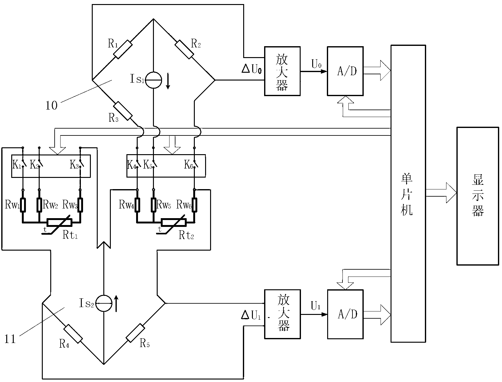
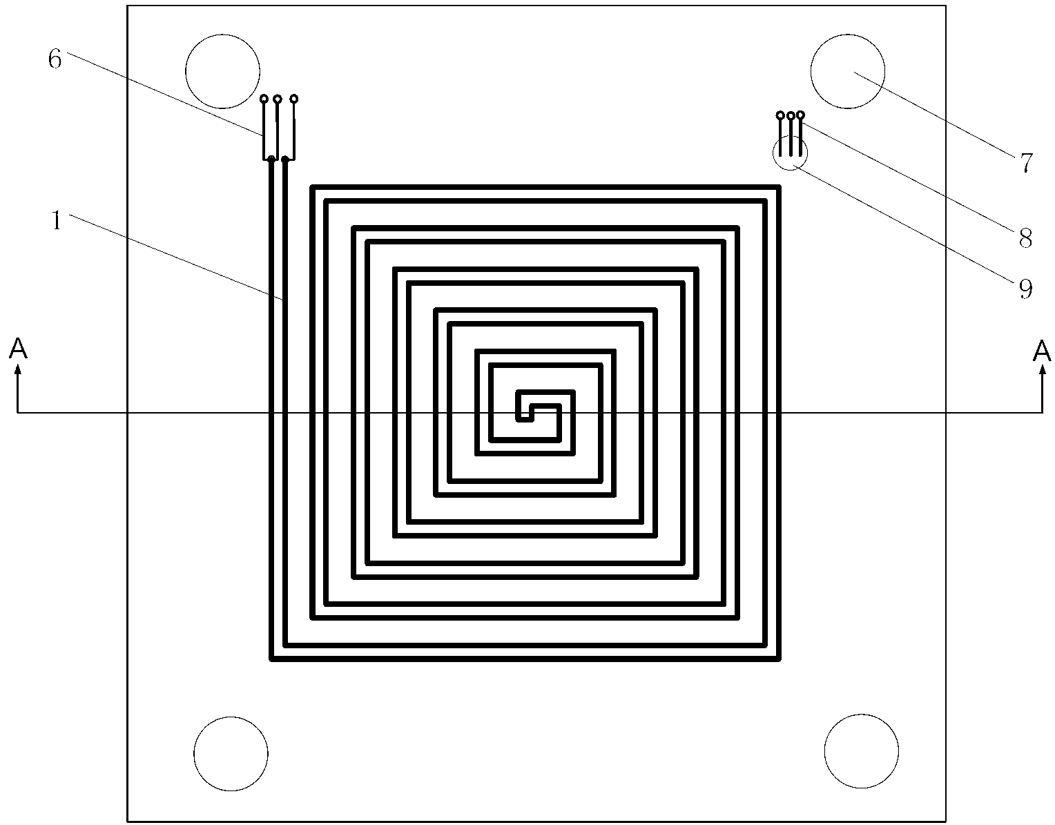
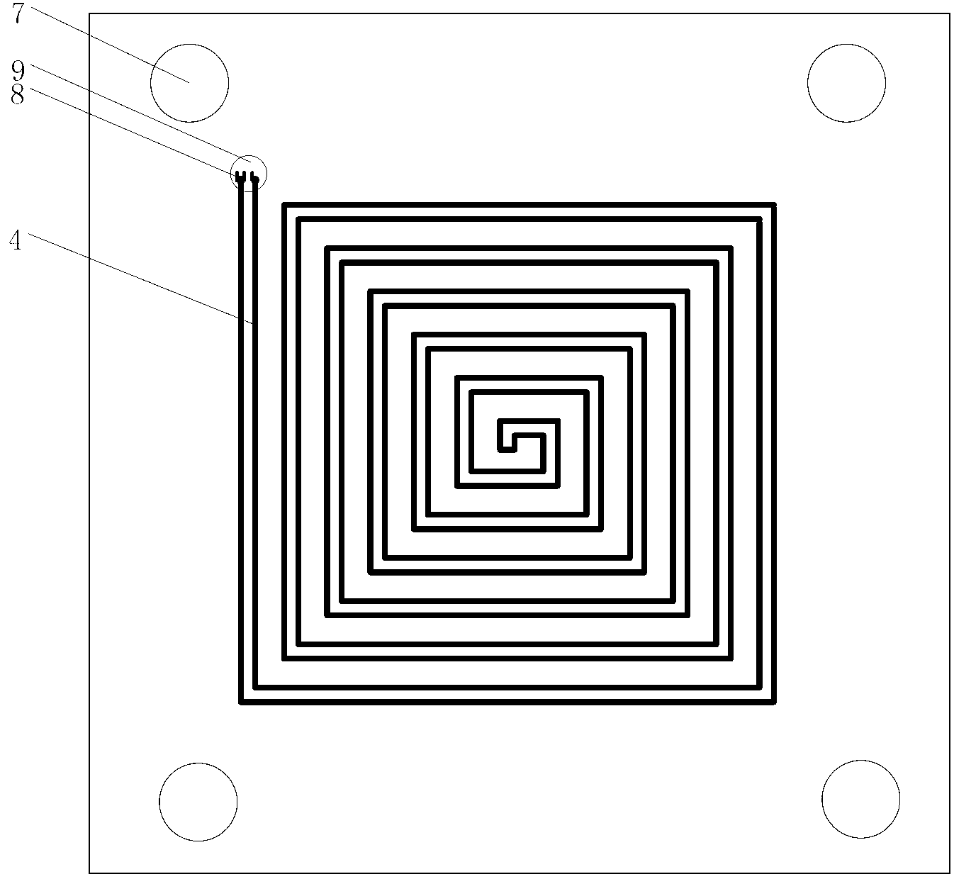
[0007] The purpose of the present invention is to solve the non-linear thermoelectric characteristics of the existing thermopile heat flow meter, the thermopile measurement circuit is easily affected by the surrounding alternating electromagnetic field, and the thermoelectric characteristics of each thermocouple cannot be guaranteed, and it cannot be individually Due to the limitations of calibration, a real-time detection device for heat flow and its real-time detection method for heat flow are proposed. The non-inductive thermal resistance temperature sensor is a thin-film, non-inductive winding upper-surface thermal resistance R made in the effective area of ​​the upper end surface 1 and the lower end surface 4 of the electrically insulating thermal resistance plate substrate 3 t2 and the lower thermal resistance R t1 ;Thermal resistance R on the upper surface t2 and the lower thermal resistance R t1 They are respectively connected to the bridge arms of the two bridge circuits of the signal processing system, and the single-chip microcomputer of the signal processing system is connected to the display system;

Method used


Image

  • Real-time heat flow detection device and real-time heat flow detection method thereof
  • Real-time heat flow detection device and real-time heat flow detection method thereof
  • Real-time heat flow detection device and real-time heat flow detection method thereof

Examples


Embodiment Construction

[0044] The invention provides a heat flow real-time detection device and a heat flow real-time detection method thereof. The present invention will be further described below in conjunction with the accompanying drawings and best implementation examples.

[0045] figure 1 The heat flow real-time detection device shown is composed of a thin-film non-inductive thermal resistance temperature sensor, a signal processing system and a display system. The signal processing system consists of a temperature measuring bridge 10, a difference measuring bridge 11, two amplifiers, two A / D converters, a single chip microcomputer, and a programmable control switch K 1 、K 2 、K 3 、K 4 、K 5 、K 6 Composed of, where the temperature measuring bridge 10 is composed of R 1 , R 2 , R 3 , The constant current source current Is of the temperature measuring bridge 10 1 and with programmable control switch K 4 、K 5 、K 6 Connect the thermal resistance value R of the upper end face t2 composi...


PUM


Abstract

The invention discloses a real-time heat flow detection device and a real-time heat flow detection method thereof, belonging to the field of process parameter detection. The real-time heat flow detection device comprises a heat flow sensor, a signal processing system and a display system, wherein high-purity metal films are subjected to vacuum ion sputtering on the upper end surface and the lower end surface of an electrically insulated heat resistance plate substrate of the heat flow sensor to form a thin-film and non-inductive metal hot resistor respectively on the upper end surface and the lower end surface through laser melting, and the outgoing line of each hot resistor adopts a three-line connection method; the signal processing system is used for processing signals output by the heat flow sensor to obtain temperature difference of the two end surfaces, thus obtaining the heat flow density; and a display device is used for displaying the value of the heat flow density. By adopting the pure metal thin films as temperature measuring materials, the heat flow sensor can fundamentally avoid the limitation that the thermoelectricity of a thermoelectric pile type thermocouple can not be guaranteed to be known and detected, and the thermoelectricity nonlinearity of the thermocouple in a thermoelectric pile and the thermoelectric potential output of a measuring circuit of the thermoelectric pile are influenced by an alternating electromagnetic field.

Description

technical field [0001] The invention belongs to the technical field of process parameter detection, and in particular relates to a heat flow real-time detection device and a heat flow real-time detection method thereof. technical background [0002] The heat flow real-time detection device is widely used in energy, chemical industry, metallurgy, construction, scientific research and other fields. Thermopile type heat flowmeter is usually used for heat flow detection. The method is to wind multiple pairs of thermocouples on the thermal resistance plate with wires of thermode materials A and B to form a so-called "thermopile". During the winding process, thermode A The connection points of , B, that is, the thermal nodes are respectively located on the two heated end faces of the thermal resistance plate. During manufacture, these thermocouples are connected in series to form a thermopile, and the output thermoelectric potential of the thermopile is E=N·E AB (t 2 ,t 1 ), E...

Claims


Application Information

Patent Timeline
IPC IPC(8): G01K17/00G01K7/20
Inventor 段泉圣张帅高秋生马登昌王丽翠左家翰罗茜文
Owner NORTH CHINA ELECTRIC POWER UNIV (BAODING)
Learn More