Mutual capacitance variation measuring circuit with high precision and low power consumption

A mutual capacitance and circuit technology, which is applied in the field of mutual capacitance measurement circuits, can solve the problems of increasing chip area and power consumption, difficulty in ensuring parameter consistency, and failure to measure the variation range, and achieves improved measurement accuracy and easy mass production control. The effect of measurement accuracy

Inactive Publication Date: 2013-09-18
上海海栎创科技股份有限公司
View PDF4 Cites 8 Cited by
  • Summary
  • Abstract
  • Description
  • Claims
  • Application Information

AI Technical Summary

Problems solved by technology

[0003] The disadvantages of the traditional detection method are: 1) Larger chip internal filter capacitors are required to ensure its stability, and the chip needs to occupy a larger area to realize these filter capacitors, so that the final chip area becomes larger and the cost increases; 2) Chip The detection of the internal voltage must use a high-speed and high-precision ADC, which will increase the area and power consumption of the chip.
3) Due to the fact that the consistency of the measured mutual capacitance and PCB parameters is difficult to guarantee in practical applications, this leads to a large variation range of the measured voltage and even exceeds the constraints of the power supply voltage, making the measurement fail, so the control and adjustment of mass production is difficult

Method used


Image

  • Mutual capacitance variation measuring circuit with high precision and low power consumption
  • Mutual capacitance variation measuring circuit with high precision and low power consumption
  • Mutual capacitance variation measuring circuit with high precision and low power consumption

Examples


Embodiment Construction

[0027] The present invention will be further described below in conjunction with the embodiments shown in the accompanying drawings.

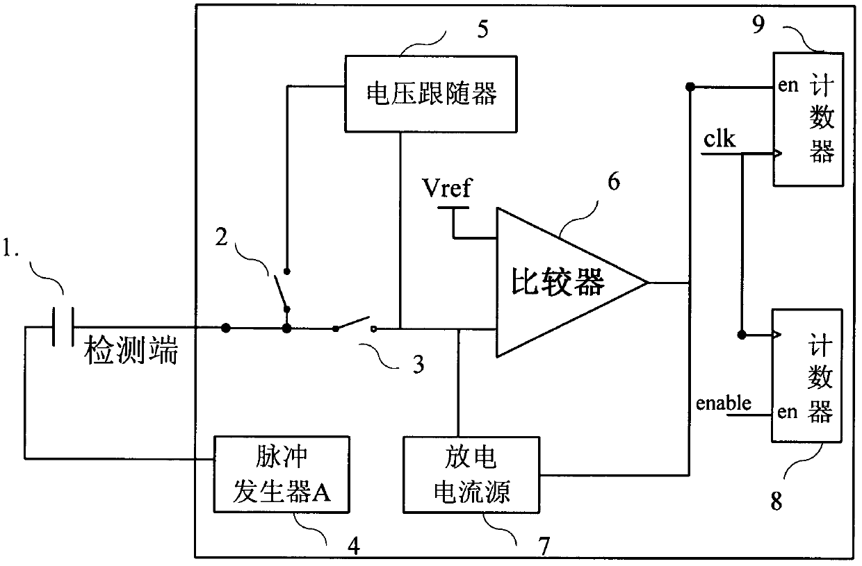
[0028] figure 1 It is the basic system circuit diagram of the measurement circuit. A measurement cycle of this measurement circuit can be divided into three steps, namely:

[0029] 1) Pulse generator clock high cycle phase

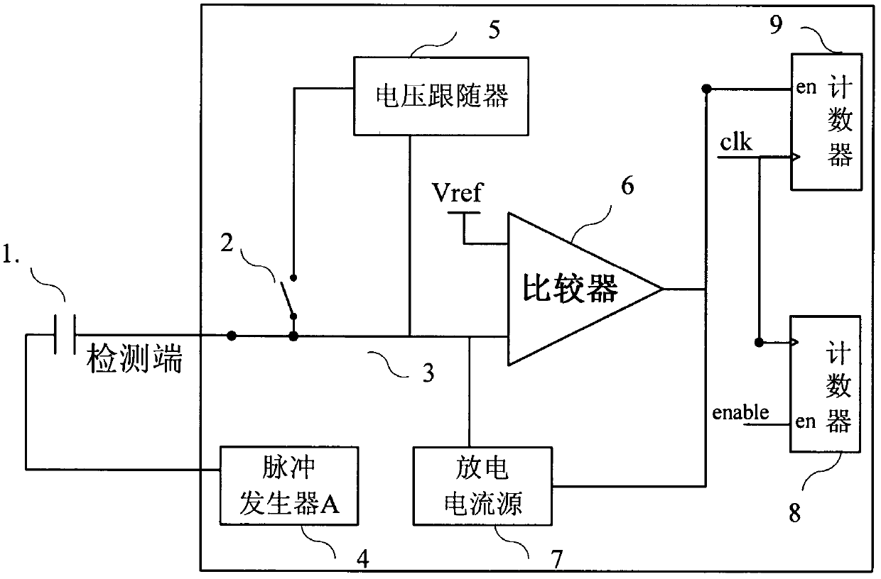
[0030] exist figure 1 , open the switch (2), close the switch (3), its equivalent circuit is as figure 2 shown. At this stage, the rising edge of the clock of the pulse generator will charge the detection terminal of the measured mutual capacitance. When the voltage exceeds Vref, the comparator will start the discharge current source to discharge it until the voltage is less than Vref. The voltage waveform at the detection terminal changes as Figure 4 The t1, t2 stages shown in.

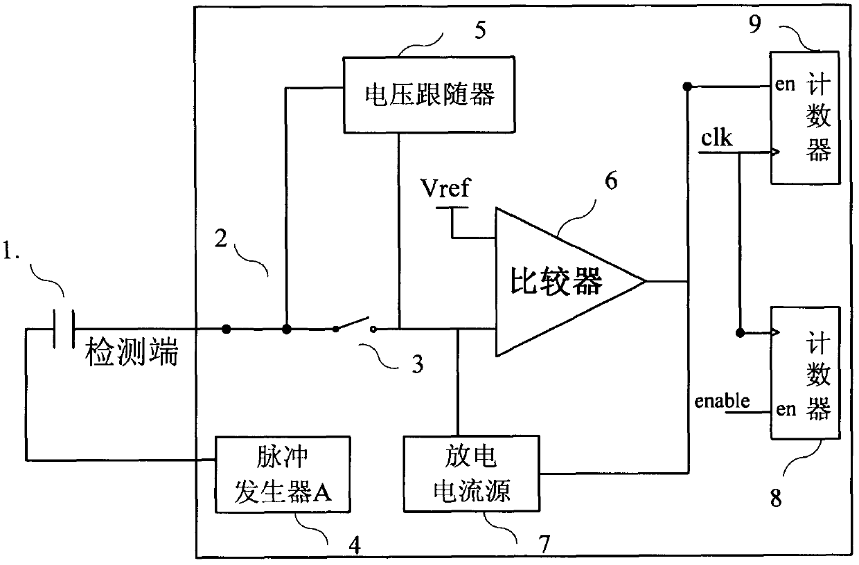
[0031] 2) Pulse generator clock low cycle phase

[0032] exist figure 1 , open the switch (3), close the switch (2), its equivalent ci...


PUM


Abstract

The invention relates to a mutual capacitance variation measuring method with a high precision and a high stability. The system is composed of a switch discharge current source, a voltage follower and an impulse generator. The impulse generator generates an impulse waveform with a fixed length of time so that a detected mutual capacitance on a high clock edge is charged. If a voltage of a detected end is more than a reference voltage, the switch discharge current source discharges so as to reduce the voltage of the detected end until the voltage is lower than the reference voltage.<{EN4}>As for different discharge time periods of a switch current source caused by different detected mutual capacitances, the variation of the detected capacitances can be detected through measuring the variation of the time periods or the ratio variation of the time periods.<{EN5}>An error accumulation and mutual elimination method is applied by the circuit so that effects of an impact of a voltage fluctuation, an error of a measuring clock and an error of a detecting circuit itself on a measuring result are minimized to a lowest point. Therefore, the measuring method is great in measuring precision and stability. Because of the error accumulation and mutual elimination, the detecting circuit does not need a circuit with the high precision, and thus a simple circuit with the low power consumption can be adopted to realize. As for different discharge time periods of a switch current source caused by different detected mutual capacitances, the variation of the detected capacitances can be detected through measuring the variation of the time periods or the ratio variation of the time periods. An error accumulation and mutual elimination method is applied by the circuit so that effects of an impact of a voltage fluctuation, an error of a measuring clock and an error of a detecting circuit itself on a measuring result are minimized to a lowest point. Therefore, the measuring method is great in measuring precision and stability. Because of the error accumulation and mutual elimination, the detecting circuit does not need a circuit with the high precision, and thus a simple circuit with the low power consumption can be adopted to realize.

Description

technical field [0001] The invention relates to a mutual capacitance measuring circuit with high precision and low power consumption and a realization method thereof. The method can be used in touch control applications, such as touch buttons, capacitive touch screens, mouse touch pads and the like. Especially suitable for multi-finger touch detection. Background technique [0002] The basic principle of the traditional mutual capacitance touch detection is to use the pulse generator to periodically charge and discharge the measured mutual capacitance, and use the current conversion circuit to copy the charging and discharging current to an internal filter capacitor, and through the detection of the filter capacitor The voltage value is used to judge the change of the measured mutual capacitance. If there is no touch, its voltage is V1. If you touch the measured mutual capacitance with a finger or a touch pen, since many magnetic force lines will stay on the finger, the m...

Claims


Application Information

Patent Timeline
Patent Type & Authority Applications(China)
IPC IPC(8): G01R27/26
Inventor 刘华贾朝辉卢昌鹏
Owner 上海海栎创科技股份有限公司
Why Eureka
Try Eureka