Voltage regulator

一种电压调节器、电压的技术,应用在调节电变量、控制/调节系统、仪器等方向,能够解决输出电压的下降难以立即对应、差动放大电路104瞬态响应特性差等问题,达到改善瞬态响应特性、减小输出电压的下降的效果

Inactive Publication Date: 2013-09-18
SII SEMICONDUCTOR CORP
View PDF7 Cites 7 Cited by
  • Summary
  • Abstract
  • Description
  • Claims
  • Application Information

AI Technical Summary

Problems solved by technology

[0008] However, in the voltage regulator including the conventional output current detection circuit, since the load current is detected by using the output signal of the differential amplifier circuit 104 and the bias current of the differential amplifier circuit 104 is controlled, it is difficult to respond immediately to the drop of the output voltage. correspond
That is, there is a problem that the transient response of the differential amplifier circuit 104 when the drop in the output voltage is detected due to the decrease in the bias current of the differential amplifier circuit 104 when the load current is switched from a light load to a heavy load Poor characteristics

Method used


Image

  • Voltage regulator
  • Voltage regulator
  • Voltage regulator

Examples


no. 1 approach 〉

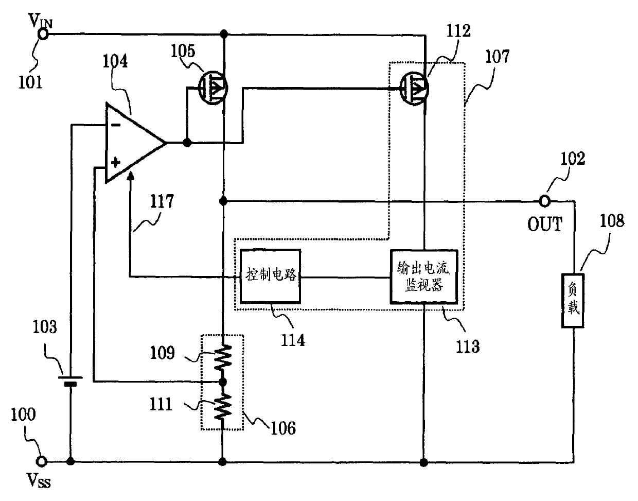
[0020] figure 1 is a circuit diagram showing a voltage regulator including the output current detection circuit of the first embodiment. The voltage regulator of this embodiment is composed of a reference voltage circuit 103 , a differential amplifier circuit 104 , an output transistor 105 , a voltage dividing circuit 106 , an output current detection circuit 107 , a resistor 151 and a capacitor 152 . The output current detection circuit 107 is composed of a detection transistor 112 , an output current monitoring circuit 113 , and a control circuit 114 .

[0021] Next, connection of element circuits of the voltage regulator of this embodiment will be described.

[0022] The output terminal of the reference voltage circuit 103 is connected to the inverting input terminal of the differential amplifier circuit 104 . The voltage dividing circuit 106 is provided between the output terminal 102 and the Vss terminal 100 , and its output terminal is connected to the non-inverting i...

no. 2 approach 〉

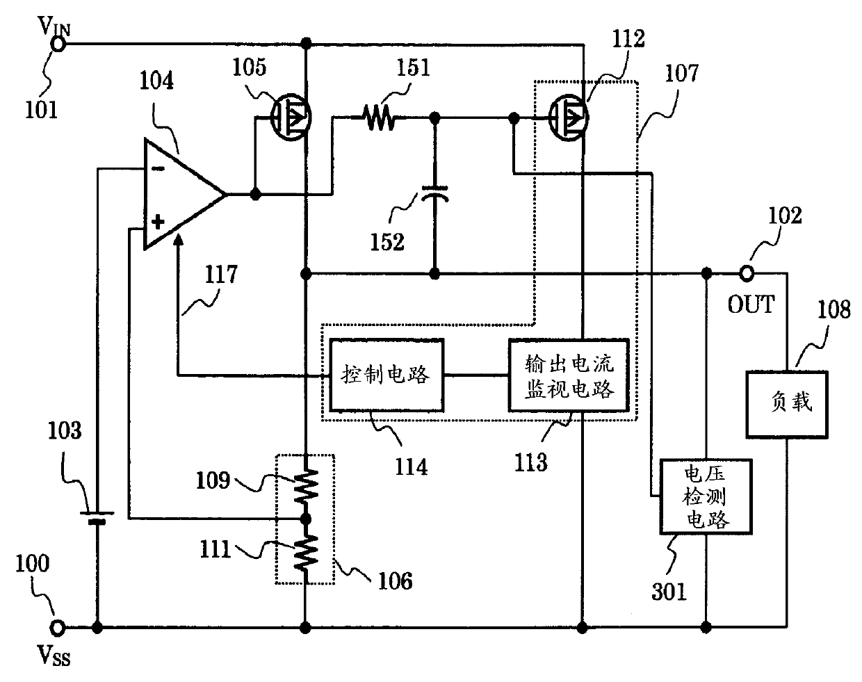
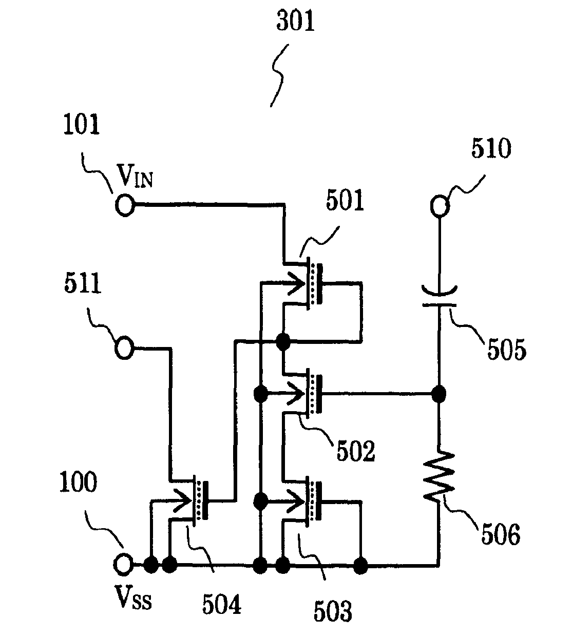
[0030] image 3 is a circuit diagram showing a voltage regulator including the output current detection circuit of the second embodiment. In the voltage regulator of this embodiment, a voltage detection circuit 301 is added to the circuit of the first embodiment. The voltage detection circuit 301 is provided between the output terminal 102 and the Vss terminal 100 , and the output terminal is connected to the gate of the detection transistor 112 .

[0031] Next, the operation of the voltage regulator of the second embodiment will be described.

[0032] When the load 108 changes from a light load to a heavy load, the voltage detection circuit 301 receives a change in the output voltage of the output terminal 102 and outputs a voltage and current for directly reducing the gate voltage of the detection transistor 112 . Therefore, a current can flow through the output current monitoring circuit 113 by the detection transistor 112 . As a result, the bias current of the different...

no. 3 approach 〉

[0038] Figure 4 is a circuit diagram showing a voltage regulator including the output current detection circuit of the third embodiment. In the voltage regulator of the present embodiment, in the circuit of the second embodiment, the output of the voltage detection circuit 301 is input to the control circuit 114 via a logic circuit 401 (for example, an OR circuit).

[0039] Next, the operation of the voltage regulator of the third embodiment will be described.

[0040]When the load 108 changes from a light load to a heavy load, the voltage detection circuit 301 receives a change in the output voltage of the output terminal 102, and outputs a signal for increasing the bias current of the differential amplifier circuit 104 to the control circuit 114 via the logic circuit 401. . The logic circuit 401 takes the logical sum (in the case of an OR circuit) of the signal of the voltage detection circuit 301 and the output voltage of the output current monitoring circuit 113 , and o...


PUM


Abstract

Provided is a voltage regulator having improved transient response characteristics even when a load current is switched from a light load to a heavy load. The voltage regulator includes, to a gate of a detection transistor constituting an output current detection circuit: a resistive element for interrupting the gate of the detection transistor from an output terminal of a differential amplifier circuit in an AC manner; and a capacitive element connected to an output terminal of the voltage regulator in an AC manner.

Description

technical field [0001] The present invention relates to voltage regulators, and more specifically, to improvement of transient response characteristics when output current fluctuates. Background technique [0002] Figure 6 It is a voltage regulator including a conventional output current detection circuit. The differential amplifier circuit 104 controls the gate-source voltage of the output transistor 105 by comparing the output voltage of the reference voltage circuit 103 and the output voltage of the voltage divider circuit 106 so that the voltage of the output terminal 102 becomes a desired voltage. The output current detection circuit 107 includes a detection transistor 112 , an output current monitoring circuit 113 and a control circuit 114 . [0003] Here, when the output voltage 102 of the voltage regulator drops due to an increase in the load current, the differential amplifier circuit 104 operates to increase the gate-source voltage of the output transistor 105 . ...

Claims


Application Information

Patent Timeline
Patent Type & Authority Applications(China)
IPC IPC(8): G05F1/565
CPCG05F1/575G05F1/10G05F3/02G05F3/24
Inventor 藤村学井村多加志小林裕二
Owner SII SEMICONDUCTOR CORP
Why Eureka
Try Eureka