
Layout Layer Design Method of Semiconductor Chip and Mask Plate

A design method and semiconductor technology, which is applied in semiconductor/solid-state device manufacturing, photolithographic process of patterned surface, and original parts used in photomechanical processing, etc., which can solve the problems of low optical accuracy, short cycle time, and low computational efficiency, etc. problem, to achieve the effect of improving calculation efficiency, reducing graphics area, and improving accuracy

Active Publication Date: 2016-08-31
SHANGHAI HUALI MICROELECTRONICS CORP
View PDF2 Cites 0 Cited by
  • Summary
  • Abstract
  • Description
  • Claims
  • Application Information

AI Technical Summary

Problems solved by technology

[0009] The purpose of the present invention is to provide a semiconductor chip layout layer design method and its mask plate to solve the problems of low accuracy, low calculation efficiency and short period of existing optical proximity correction

Method used


Image

  • Layout Layer Design Method of Semiconductor Chip and Mask Plate

Examples


Embodiment Construction

[0019] The layout layer design method of the semiconductor chip and its mask plate proposed by the present invention will be further described in detail below in conjunction with the accompanying drawings and specific embodiments. Advantages and features of the present invention will be apparent from the following description and claims. It should be noted that all the drawings are in a very simplified form and use imprecise scales, and are only used to facilitate and clearly assist the purpose of illustrating the embodiments of the present invention.

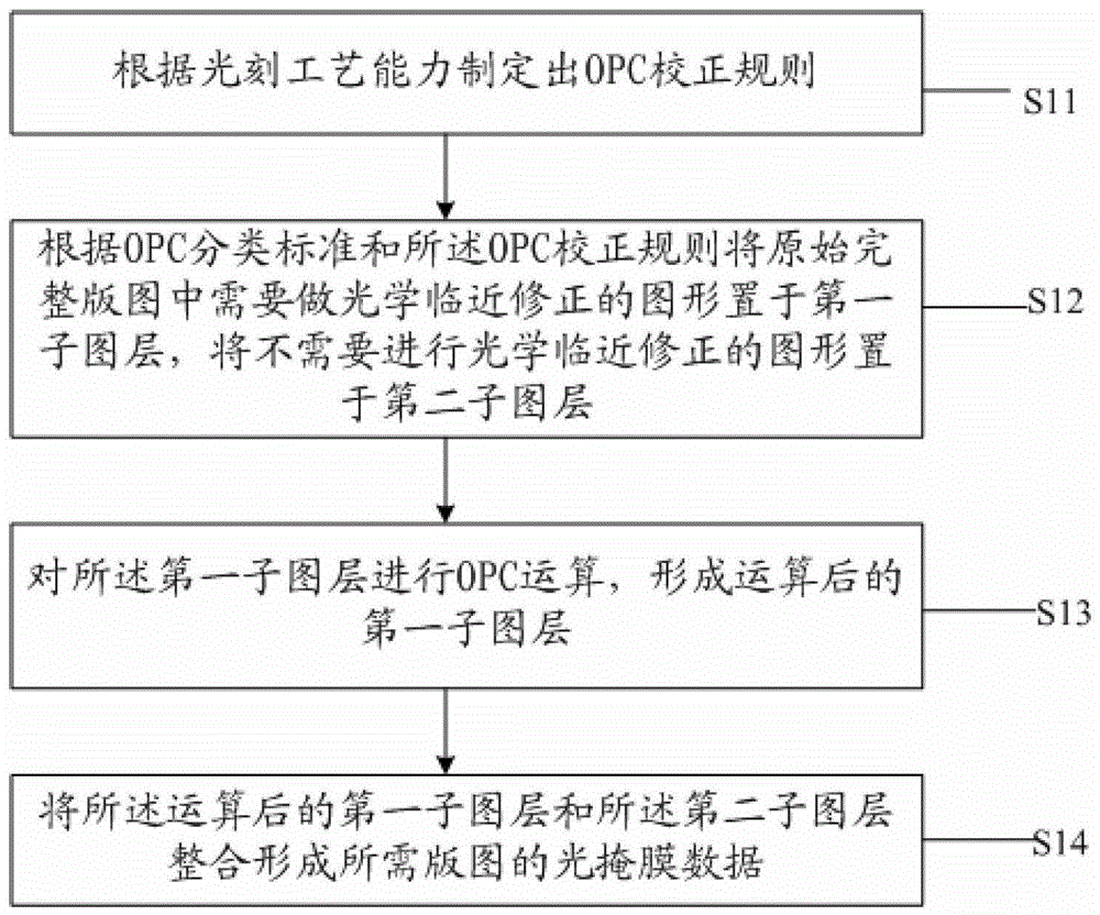
[0020] The core idea of ​​the present invention is that the semiconductor chip layout layer design method provided by the present invention only needs to perform optical proximity correction on the first sub-layer, and does not perform any processing on the second sub-layer. The actual calculation amount, The calculation graphic area is greatly reduced, the calculation efficiency is greatly improved, the work efficiency of the ...


PUM


Abstract

The invention provides a layout-layer designing method of a semiconductor chip, which comprises the following steps of making an OPC (Optical Proximity Correction) rule according to photo-etching process capability; placing graphs needing OPC in an original complete layout onto a first sub-layer according to an OPC classifying standard and the OPC rule, and placing graphs needing no OPC onto a second sub-layer; carrying out OPC operation on the first sub-layer to form the operated first sub-layer; and integrating the operated first sub-layer with the second sub-layer to form the photo-masking data of the required layout. The invention also provides a masking plate utilizing the layout-layer designing method of the semiconductor chip. In the layout-layer designing method of the semiconductor chip provided by the invention, the OPC for the first sub-layer only needs to be carried out without any processing on the second sub-layer, so that the actual calculated amount and the calculated graph area are greatly reduced, the calculating efficiency is greatly improved, the work efficiency of an operation server is improved, and the publication period of a product is shortened.

Description

technical field [0001] The invention relates to the technical field of semiconductor manufacturing, in particular to a layout layer design method of a semiconductor chip and a mask plate thereof. Background technique [0002] In advanced semiconductor manufacturing processes, optical proximity correction is required for design layouts to improve the manufacturability of graphics. Especially in the deep submicron semiconductor chip manufacturing process, since the line width of the key pattern is much smaller than the wavelength of the light source, the diffraction effect of light will cause distortion of the pattern projected on the silicon wafer by the mask, and even cause the pattern to exceed the acceptable range. graphics distortion. Typical effects are: wire end shortening, rounded corners and critical dimension shifts, etc. The effect of this optical diffraction distortion is affected by the surrounding graphics environment, which is called optical proximity effects....

Claims


Application Information

Patent Timeline
Patent Type & Authority Patents(China)
IPC IPC(8): H01L21/033G03F1/36
Inventor 张亮毛智彪曹永峰俞柳江于世瑞
Owner SHANGHAI HUALI MICROELECTRONICS CORP
Learn More