Series direct-current motor four-switch topological device and control method thereof

A series-excited motor and four-switch technology, applied in the direction of electronic commutation motor control, control system, stop device, etc., can solve the problems of loose mechanical connection between terminals and devices, faulty terminals, and large mechanical adhesion of cables, etc.

Inactive Publication Date: 2013-09-18
YANGZHOU DADE JIDIAN TECH
View PDF6 Cites 6 Cited by
  • Summary
  • Abstract
  • Description
  • Claims
  • Application Information

AI Technical Summary

Problems solved by technology

At the same time, when the current is high, one of the faults of the speed regulating device is the fault of the wiring terminal.
This is because in the case of hundreds of thousands of amperes, even if a material such as copper is used, the heat of the terminal itself is still very serious
Moreover, the mechanical adhesion of the connected cable is also relatively large, which may easily cause the mechanical connection between the terminal and the inside of the device to be loose, resulting in a large contact resistance, resulting in serious heat generation and burning of the connection between the terminal and the inside of the device

Method used


Image

  • Series direct-current motor four-switch topological device and control method thereof
  • Series direct-current motor four-switch topological device and control method thereof

Examples


Embodiment 1

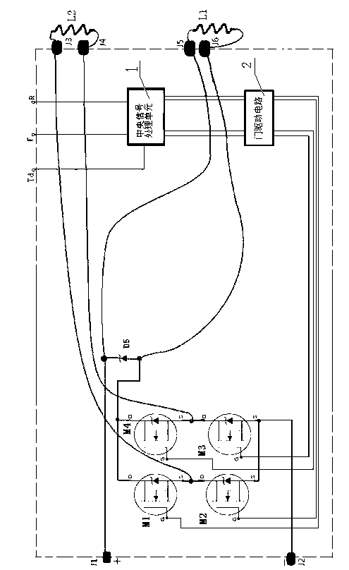
[0020] Such as figure 1 As shown, the control device for realizing the electronic commutation of the series-excited motor is provided with a full-bridge circuit composed of four semiconductor switching elements M1, M2, M3 and M4, a central signal processing unit 1, a gate drive circuit 2, a continuous flow diode D5. The common end of the two lower arms M2 and M3 of the full-bridge circuit is connected to the negative terminal J2 of the DC bus, the winding L2 of the series-wound motor is connected between the two output ends of the full-bridge circuit, and the winding L1 of the series-wound motor is connected to the DC Between the positive terminal J1 of the bus and the common terminals of the two upper arms M1 and M4 of the full bridge circuit, the cathode of the freewheeling diode D5 is connected to the positive terminal J1 of the DC bus, and the anode of the freewheeling diode D5 is connected to the two upper arms of the full bridge circuit The common terminal of M1 and M4 ...

Embodiment 2

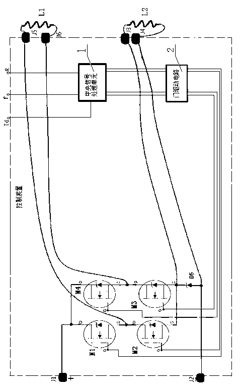
[0034] Such as figure 2 As shown, the control device for realizing the electronic commutation of the series-excited motor is equipped with a full-bridge circuit composed of semiconductor switching elements M1, M2, M3 and M4, a central signal processing unit 1, a gate drive circuit 2, and a freewheeling diode D5.

[0035] The common ends of the two upper arms M1 and M4 of the full-bridge circuit are connected to the positive terminal J1 of the DC bus, the winding L1 of the series-wound motor is connected between the two output ends of the full-bridge circuit, and the winding L2 of the series-wound motor is connected to the DC bus Between the negative terminal J2 and the common terminals of the two lower arms M2 and M3 of the full bridge circuit, the anode of the freewheeling diode D5 is connected to the negative terminal J2 of the DC bus, and the cathode of the freewheeling diode D5 is connected to the two lower arms of the full bridge circuit. The common end of the arms M2 a...


PUM


Abstract

The invention discloses a series direct-current motor four-switch topological device and a control method thereof, and relates to the technical field of brushed direct-current motors. The series direct-current motor four-switch topological device comprises a full-bridge circuit, a center signal processing unit, a gate drive circuit and a flyback diode, wherein the full-bridge circuit comprises semiconductor switch elements. The full-bridge circuit which is composed of the semiconductor switch elements is utilized to control one of windings of the series direct-current motor, then the other winding is in series connection between the full-bridge circuit and bus directly, and the flyback diode is in parallel connection with the winding reversely. Since one of two power supply switches of the full-bridge circuit can be selected to control current direction of the windings connected to the full-bridge circuit, reversing of electromagnetic torque of the motor is realized.

Description

technical field [0001] The invention relates to the technical field of DC brush motor control. Background technique [0002] In the field of electric drive, DC series motors are widely used because of the proportional relationship between the torque and the square of the current. However, for hundreds of amperes and large current applications, the original speed control device needs an electromagnetic contactor and cannot realize mechanical energy feedback, which has become a shackle for further performance improvement of the DC series excitation motor drive system. Due to the high price of high-current semiconductor switches, how to minimize the number of semiconductor switches to achieve a high-performance speed control device is also an important goal. At the same time, when the current is high, one of the faults of the speed regulating device is the fault of the wiring terminal. This is because in the case of hundreds of thousands of amperes, even if a material such as...

Claims


Application Information

Patent Timeline
Patent Type & Authority Applications(China)
IPC IPC(8): H02P6/00H02P6/24H02P9/30
Inventor 周斌欣成刚马明明赵国良毛炫辉
Owner YANGZHOU DADE JIDIAN TECH
Why Eureka
Try Eureka