
Relaxation oscillator for increasing frequency-control current linearity

A relaxation oscillator and current control technology, applied in the electric pulse generator circuit, electrical components, generating electric pulses, etc., can solve the problems of large deviations in the oscillator period and duty cycle, inconsistent capacitance values, etc., to achieve Effects of reducing delay, improving linearity, and increasing amplitude

Active Publication Date: 2013-09-18
SOUTHEAST UNIV
View PDF4 Cites 25 Cited by
  • Summary
  • Abstract
  • Description
  • Claims
  • Application Information

AI Technical Summary

Problems solved by technology

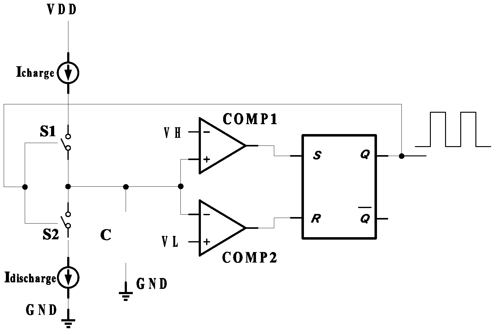
[0028] Figure 4 The current-controlled relaxation oscillator with dual ground timing capacitors shown has deficiencies while reducing the delay. For example, there are process deviations in the manufacturing process of capacitors C1 and C2, resulting in two capacitors whose capacitances are not equal. , Therefore, there is a deviation in the cycle and duty cycle of the oscillator due to process jitter. If the capacitance deviation of capacitors C1 and C2 is large, the cycle and duty cycle of the oscillator will deviate greatly, so it is necessary to A Current-Controlled Relaxation Oscillator with Dual Grounded Timing Capacitors Improves

Method used


Image

  • Relaxation oscillator for increasing frequency-control current linearity
  • Relaxation oscillator for increasing frequency-control current linearity
  • Relaxation oscillator for increasing frequency-control current linearity

Examples


Embodiment Construction

[0055] refer to Figure 6 , The relaxation oscillator of the present invention includes a charging and discharging circuit 1 , a floating charging and discharging capacitor 2 , and a control circuit 3 , and the floating charging and discharging capacitor 2 is connected between the charging and discharging circuit 1 and the control circuit 3 .

[0056] Charge and discharge circuit 1 includes a current source I 1 , current source I 2 , current source I 3 , current source I 4 And control switch S1, control switch S2, control switch S3, control switch S4, current source I 1 The negative pole and the current source I 3 The negative pole is connected to the power supply VDD, the current source I 1The positive pole of the control switch S1 is connected to one end of the control switch S1, the other end of the control switch S1 is connected to one end of the control switch S2, and the other end of the control switch S2 is connected to the current source I 2 the negative pole of ...


PUM


Abstract

The invention discloses a relaxation oscillator for increasing frequency-control current linearity. The relaxation oscillator comprises a charge and discharge circuit, a control circuit and a floating charge and discharge capacitor arranged between the charge and discharge circuit and the control circuit. The control circuit detects voltage of the floating charge and discharge capacitor and outputs a control signal. The output signal of the oscillator is determined by only the charge process of the floating charge and discharge capacitor, so that complete-period delay of the oscillator is decreased and frequency-control current linearity of the oscillator is increased. The floating charge and discharge capacitor is formed by parallelly connecting two equal capacitors C1 and C2, and two pole plates of the capacitors C1 and C2 are cross-connected with each other; two ends of the floating charge and discharge capacitor are symmetrical, so that the influence of micro stray capacitance at two ends of the floating charge and discharge capacitor upon the output of the oscillator is decreased.

Description

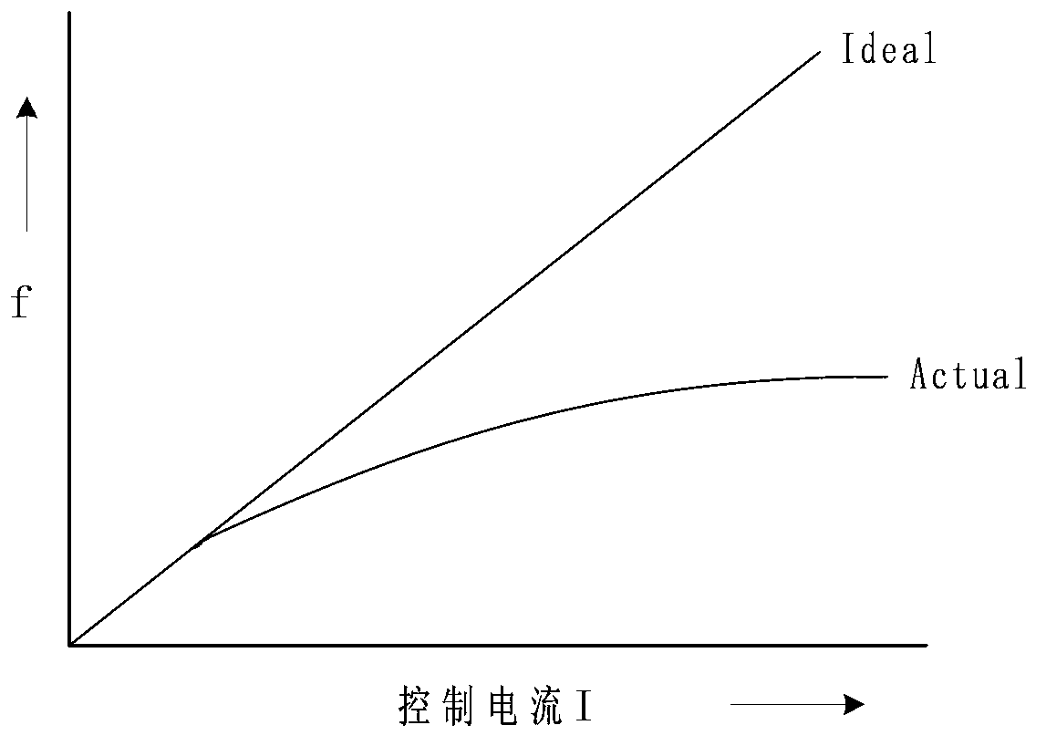
technical field [0001] The invention relates to the field of CMOS integrated circuits, in particular to a relaxation oscillator which improves the linearity of frequency-controlled current. Background technique [0002] In VLSI, the clock signal is essential. Generally, the clock signal is generated by the oscillator, and the relaxation oscillator is the most widely used oscillator. It has a simple structure, low cost, and easy integration. , and the power consumption is relatively small. [0003] Controllable relaxation oscillators are extremely useful circuits, especially in applications such as modulation and demodulation, clock recovery in data storage systems, etc. For modulation and demodulation, in order to reduce distortion, the oscillator frequency-control current is required to have a high linearity, and maximizing the oscillator frequency also requires the oscillator frequency-control current to have good control linearity. In clock recovery circuits, small jitt...

Claims


Application Information

Patent Timeline
IPC IPC(8): H03K3/011H03K3/023
Inventor 孙伟锋张允武林吉勇宋慧滨祝靖陆生礼时龙兴
Owner SOUTHEAST UNIV
Learn More