Supercharge Your Innovation With Domain-Expert AI Agents!

Method for separating liquid from suspended matter in a sludge and device for same

A technology for suspended matter and mud, applied in separation methods, chemical instruments and methods, precipitation separation, etc., can solve problems such as blockage and long time, and achieve low power consumption and cost saving effects

Active Publication Date: 2013-09-18
OREGE
View PDF8 Cites 7 Cited by
  • Summary
  • Abstract
  • Description
  • Claims
  • Application Information

AI Technical Summary

Problems solved by technology

[0013] Such a method, besides being time-consuming, also uses a sufficiently complex device, which is the source of many blockages

Method used


Image

  • Method for separating liquid from suspended matter in a sludge and device for same
  • Method for separating liquid from suspended matter in a sludge and device for same
  • Method for separating liquid from suspended matter in a sludge and device for same

Examples


Embodiment Construction

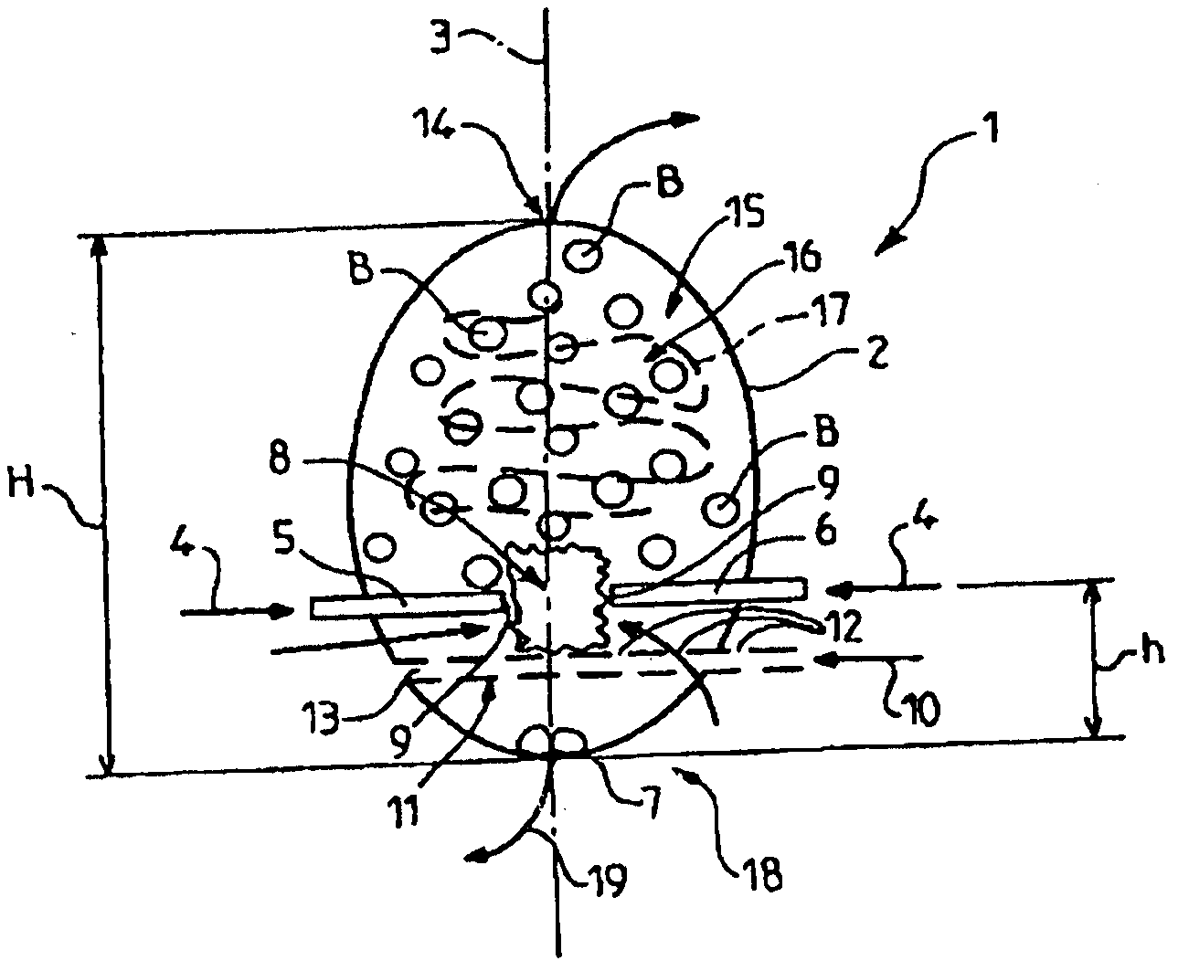
[0067] figure 1 The principles of the method of separation between liquid and solids of a slurry according to embodiments of the invention described more particularly herein are shown.

[0068] In a reactor 1 formed by an oblong shell 2 elongated around an axis 3 with a small volume v, for example about 50 liters, injection is via two opposing nozzles 5, 6 symmetrical with respect to the shell axis 3 Waste liquid (arrow 4).

[0069] These nozzles are located in the bottom part of the housing, for example at a distance h from the housing bottom 7 of between one fifth and one third of the height H of the housing.

[0070] These two nozzles positioned opposite each other allow the pressurized feed of a water stream with a high load of dry matter (MS) (eg MS 10% / τ of the total weight), which causes a strong impact of the two streams where they meet in zone 8 .

[0071] In other words, the pumping of external water (not shown) introduced into the shell of the small-scale reactor...


PUM


Abstract

The invention relates to a method for separating the liquid part from the suspended matter in a sludge supplied in a continuous flow at a flow rate of QEB = V / hour. The flow is divided into at least two partial flows which are sprayed on top of one another into a sealed chamber of volume v < V / 20, simultaneously injecting air therein at a flow rate d, said chamber being kept under overpressure conditions. The suspended matter of the thus treated flow is then left to decant in a collection container, with the cake or solid part falling to the bottom and separating from the liquid part which is continuously discharged.

Description

technical field [0001] The present invention relates to flow rate Q EB A method of separation between the liquid portion of the slurry and the suspended matter supplied by a continuous flow of = V / h. [0002] The invention thus allows the removal of almost all suspended matter in order to bring them down below a certain threshold. [0003] The invention also relates to a slurry treatment plant for carrying out such a method. [0004] The invention finds particularly important, though not exclusive, application in the field of mud dewatering and water clarification. [0005] Surprisingly, the present invention stems from exploiting the very high energy in the liquid muddy medium, which will allow inter alia to attack the colloidal structures within such waste liquids. [0006] In fact, colloids are present in solid sludge (in its organic fraction), but also in water. [0007] In particular, it is these colloids that give a cloudy color that makes separation between liquid a...

Claims


Application Information

Patent Timeline
IPC IPC(8): C02F1/54C02F11/14
CPCB01D21/01B01D21/02B01D21/286C02F1/20C02F1/54C02F1/74C02F11/12C02F2209/40C02F2301/066C02F2303/06C02F11/147C02F11/14
Inventor P·卡波M·洛佩兹P·让德罗
Owner OREGE
Features
  • R&D
  • Intellectual Property
  • Life Sciences
  • Materials
  • Tech Scout
  • Unparalleled Data Quality
  • Higher Quality Content
  • 60% Fewer Hallucinations
Learn More