Optically pumped magnetometer, magnetoencephalography meter, and MRI device

A magnetometer and optical pump technology, applied in magnetic resonance measurement, medical science, diagnosis, etc., can solve the problems of setting heaters, inability to uniformly heat the tank, and complexity, and achieve the effect of uniform heating of the tank

Inactive Publication Date: 2013-09-18
SUMITOMO HEAVY IND LTD
View PDF9 Cites 3 Cited by
  • Summary
  • Abstract
  • Description
  • Claims
  • Application Information

AI Technical Summary

Problems solved by technology

[0007] However, as described above, in the case of heating the tank with a heater, it is difficult to install the heater in the part of the tank where the transmitted laser beam passes through, so the tank may not be heated uniformly, resulting in a decreas

Method used


Image

  • Optically pumped magnetometer, magnetoencephalography meter, and MRI device
  • Optically pumped magnetometer, magnetoencephalography meter, and MRI device
  • Optically pumped magnetometer, magnetoencephalography meter, and MRI device

Examples


Embodiment Construction

[0023] Hereinafter, preferred embodiments of the present invention will be described in detail with reference to the drawings. In addition, in the following description, the same code|symbol is attached|subjected to the same or equivalent element, and repeated description is abbreviate|omitted.

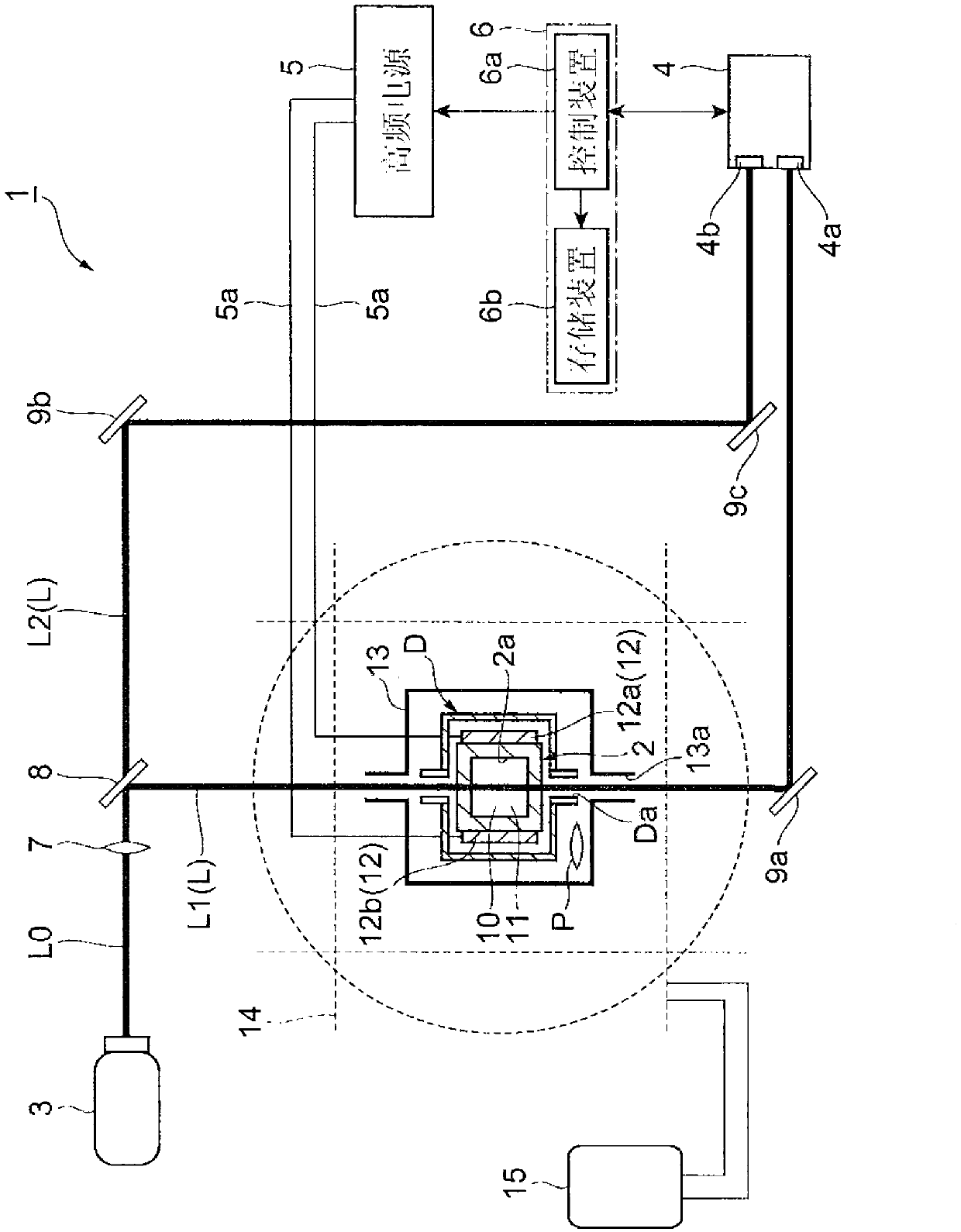
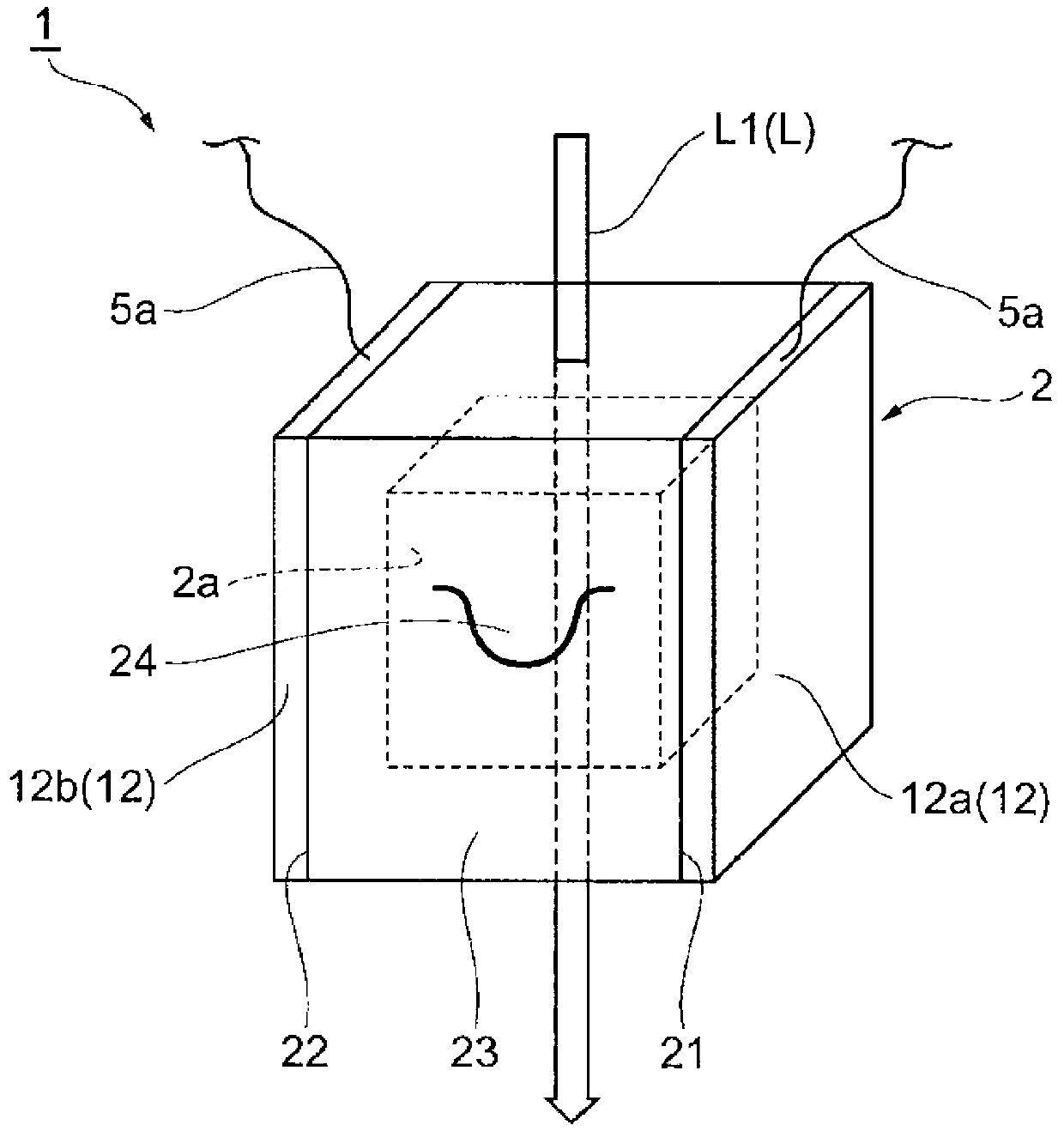
[0024] figure 1 A schematic configuration diagram showing an optically pumped magnetometer according to an embodiment of the present invention, figure 2 to represent figure 1 Schematic perspective view of the glass tank of an optically pumped magnetometer. Such as figure 1 , figure 2 As shown, the optically pumped magnetometer 1 of this embodiment uses optical pumping (spin polarization) to measure the magnetic field of a weak magnetic field source (measuring object) P, and is used, for example, in magnetoencephalography or MRI (Magnetic Resonance Imaging) devices. As a high-sensitivity magnetometer.

[0025] A magnetoencephalograph is a device that detects an extremely weak m...


PUM


Abstract

The present invention provides an optically pumped magnetometer, a magnetoencephalography meter, and an MRI device. The optically pumped magnetometer is used for measuring a magnetic field of a subject of interest by utilizing optical pumping, and comprises: a non-magnetic cell in which at least an alkali metal is encapsulated and which has light transmissivity and heat resistance; a laser beam emission unit which emits a laser beam toward the cell to achieve the optical pumping of at least the alkali metal; a detection unit which receives the transmitted laser beam that has been transmitted through the cell and which detects a detection signal associated with the magnetic field; and a high-frequency voltage application unit which applies a high-frequency voltage to a pair of application sections arranged in the cell and which heats the cell by dielectric heating.

Description

technical field [0001] The invention relates to an optical pump magnetometer, a magnetoencephalograph and an MRI device. Background technique [0002] In recent years, optically pumped magnetometers using alkali metals have been developed as high-sensitivity magnetometers replacing SQUID sensors. Optically pumped magnetometers do not require a cooling function and can greatly reduce the running cost of SQUID sensors. From this point of view, it is expected that they can be applied to magnetoencephalographs, MRI devices, and the like. [0003] In such an optically pumped magnetometer, laser light is irradiated to a cell in which an alkali metal is sealed, whereby the alkali metal in the cell is spin-polarized. And in this state, a detection signal about the magnetic field of the measurement object is detected by receiving the transmitted laser light transmitted through the groove. Here, when the alkali metal is spin-polarized, it is necessary to heat the tank for vaporizing...

Claims


Application Information

Patent Timeline
IPC IPC(8): G01R33/26A61B5/05A61B5/055
CPCG01R33/26A61B5/245A61B5/05
Inventor 高桥伸明
Owner SUMITOMO HEAVY IND LTD
Why Eureka
Try Eureka