
Reciprocating dry-type magnetic separator

A magnetic separation, reciprocating technology, applied in the direction of magnetic separation, solid separation, chemical instruments and methods, etc., can solve the problems of waste of water resources, damage to the box, waste of raw materials, etc., to facilitate separation, reduce machine failure rate, The effect of easy maintenance

Active Publication Date: 2013-09-25
江苏旌凯中科超导高技术有限公司
View PDF7 Cites 6 Cited by
  • Summary
  • Abstract
  • Description
  • Claims
  • Application Information

AI Technical Summary

Problems solved by technology

As a kind of wet magnetic separator, the body in this patent application inevitably has the disadvantages of energy consumption and water resource waste that other wet magnetic separators have. Magnetically conductive stainless steel twill tooth plate, steel ball, steel mesh or steel wool bag) are limited in strength. When used in a large amount of industrial production, it often occurs that the reciprocating box needs to be impacted by a large amount of raw ore to cause damage to the box, or due to magnetic accumulation. Unfavorable conditions such as waste of raw materials caused by the impact of the medium
In addition, according to the drawings and related text descriptions disclosed in the above-mentioned patent application documents, the magnetic field lines passing through the reciprocating box in the hydromagnetic magnetic system are not divergent. Although this kind of magnetic field is conducive to the accumulation of magnetic minerals, the magnetic field lines It is relatively dense, and the hair needles attached to the magnetic gathering medium after accumulation contain more impurities

Method used


Image

  • Reciprocating dry-type magnetic separator
  • Reciprocating dry-type magnetic separator

Examples


Embodiment Construction

[0022] The present invention will be further described below in conjunction with the accompanying drawings and embodiments.

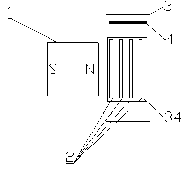
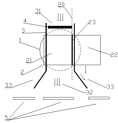
[0023] like figure 1 As shown, the present invention provides a reciprocating dry magnetic separator, comprising a superconducting magnet 1 and a sorting mechanism whose magnetic force lines diverge; the superconducting magnet 1 forms divergent magnetic force lines at two ends, and multiple The layer can penetrate the flat plate (sorting disk) of the magnetic force line; the sorting mechanism includes at least one adsorption piece 2 that moves horizontally, and there is a gap between the connected adsorption pieces 2 when there are multiple pieces; the superconducting magnet 1-magnetic end surface The lines of magnetic force pass through the adsorption sheet 2; the magnetic field strength at the adsorption sheet 2 can be above 0.1T. In order to obtain a better production effect, the field strength is preferably greater than 0.2T. The adsorption sheet 2...


PUM


Abstract

The invention provides a reciprocating dry-type magnetic separator. The reciprocating dry-type magnetic separator comprises a superconducting magnet having diverging magnetic force lines and a separation mechanism. The separation mechanism comprises at least one adsorption sheet capable of horizontal reciprocating motion. The magnetic force lines of the superconducting magnet pass through the adsorption sheet. In a horizontal direction, at least one part of the adsorption sheet is separated from a magnetic field zone of the superconducting magnet. The adsorption sheet is prepared from a non-magnetic material and is arranged vertically. The reciprocating dry-type magnetic separator has a simple structure; the magnetic force lines of the superconducting magnet pass through the adsorption sheet and the adsorption sheet and the superconducting magnet are separated so that adsorption sheet dismounting is convenient and maintenance is easy; the magnetic force lines of the superconducting magnet are diverging and magnetic minerals attached to the adsorption sheet are arranged loosely so that the nonmagnetic minerals are separated from magnetic minerals easily; and the adsorption sheet is arranged vertically so that the impact produced by raw ore on the equipment is effectively reduced and a machine failure rate is effectively reduced and continuous large-scale production is realized.

Description

technical field [0001] The invention belongs to the field of mineral separation, in particular to a reciprocating dry magnetic separator suitable for large-flow dry powder ore. Background technique [0002] Traditional wet magnetic separators have been gradually replaced by dry magnetic separators due to the large investment in equipment, serious environmental pollution, harsh working environment, and astonishing waste of energy consumption, land and water resources. At present, the dry magnetic separators developed in China are basically of drum structure. In order to improve the work efficiency and magnetic separation effect, the structure design of the machine itself is relatively complicated and occupies a large area. Once the machine fails, it is very difficult to maintain. Not only that, but there is still a gap in quality between the minerals produced by the existing dry magnetic separation equipment and the products of the wet process. It is mainly manifested in tha...

Claims


Application Information

Patent Timeline
IPC IPC(8): B03C1/02
Inventor 陈浩树徐风雨李亦然马仲英袁君辉吴敏刚
Owner 江苏旌凯中科超导高技术有限公司
Learn More