Light beam movement track control device for laser processing

A motion trajectory and control device technology, which is applied in the field of beam motion trajectory control devices for laser processing, and can solve problems such as small deflection amplitude, unsuitable processing, and small modulation motion range

Active Publication Date: 2015-02-18
张立国
View PDF7 Cites 0 Cited by
  • Summary
  • Abstract
  • Description
  • Claims
  • Application Information

AI Technical Summary

Problems solved by technology

[0003] The patent application number is 200380110303.9. The circular modulation motion of the light beam in front of the vibrating mirror is a circular motion by reflecting the modulated laser light through the mirror, and the mirror is driven by piezoelectric ceramics. The deflection range is very small, and it is difficult to process larger holes.
[0004] The patent application number is 201210460145.0. Since the flat optical element works in a swing mode, the range of modulation movement of the flat optical element to the laser beam is very small, which is not suitable for processing a large format. Smaller, the higher the cycle frequency of repeated scanning, but because the general processing graphics have certain size requirements, the cycle frequency of repeated scanning cannot be increased, which has limitations

Method used


Image

  • Light beam movement track control device for laser processing
  • Light beam movement track control device for laser processing
  • Light beam movement track control device for laser processing

Examples


Embodiment 1

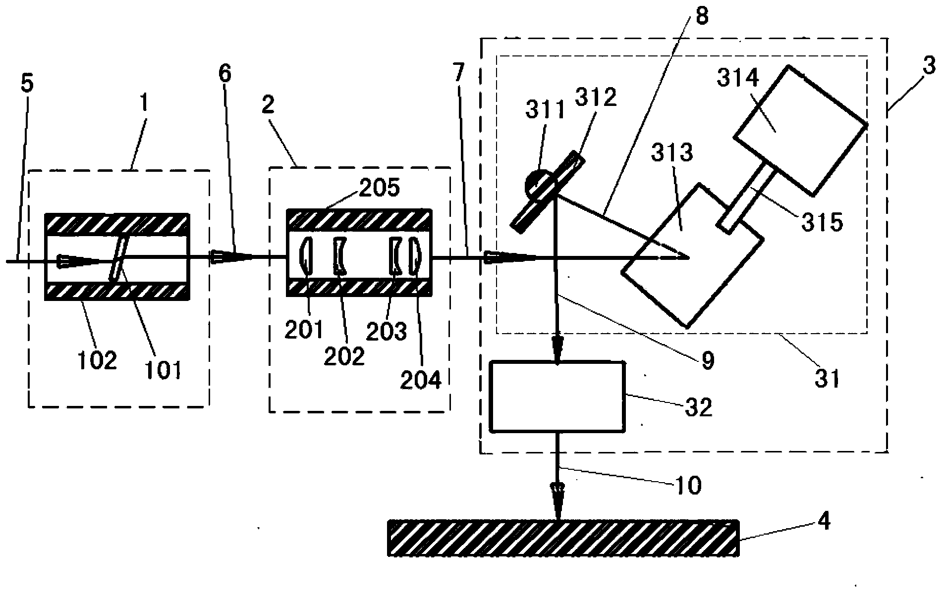
[0046] figure 1 Schematic diagram of the device structure for laser drilling through holes in copper foil, such as figure 1 As shown: the device for copper foil laser drilling through holes includes a beam transmission azimuth control module 1 , a beam movement trajectory imaging amplification module 2 and a laser focusing and focus switching module 3 .

[0047] The beam transmission azimuth control module 1 is a beam rotation modulation unit, the beam rotation modulation unit includes a beam rotation modulation sub-unit, the beam rotation modulation sub-unit includes a rotating transmission optical element and a rotating transmission optical element for driving the rotating motion drive unit. The rotating transmission optical element is a rotating flat quartz glass 101. The refractive index of the rotating flat quartz glass 101 is 1.35 to 3, preferably 1.45, and the thickness is 6 mm. Larger, the larger the beam rotation diameter. The driving device is an air-floating holl...

Embodiment 2

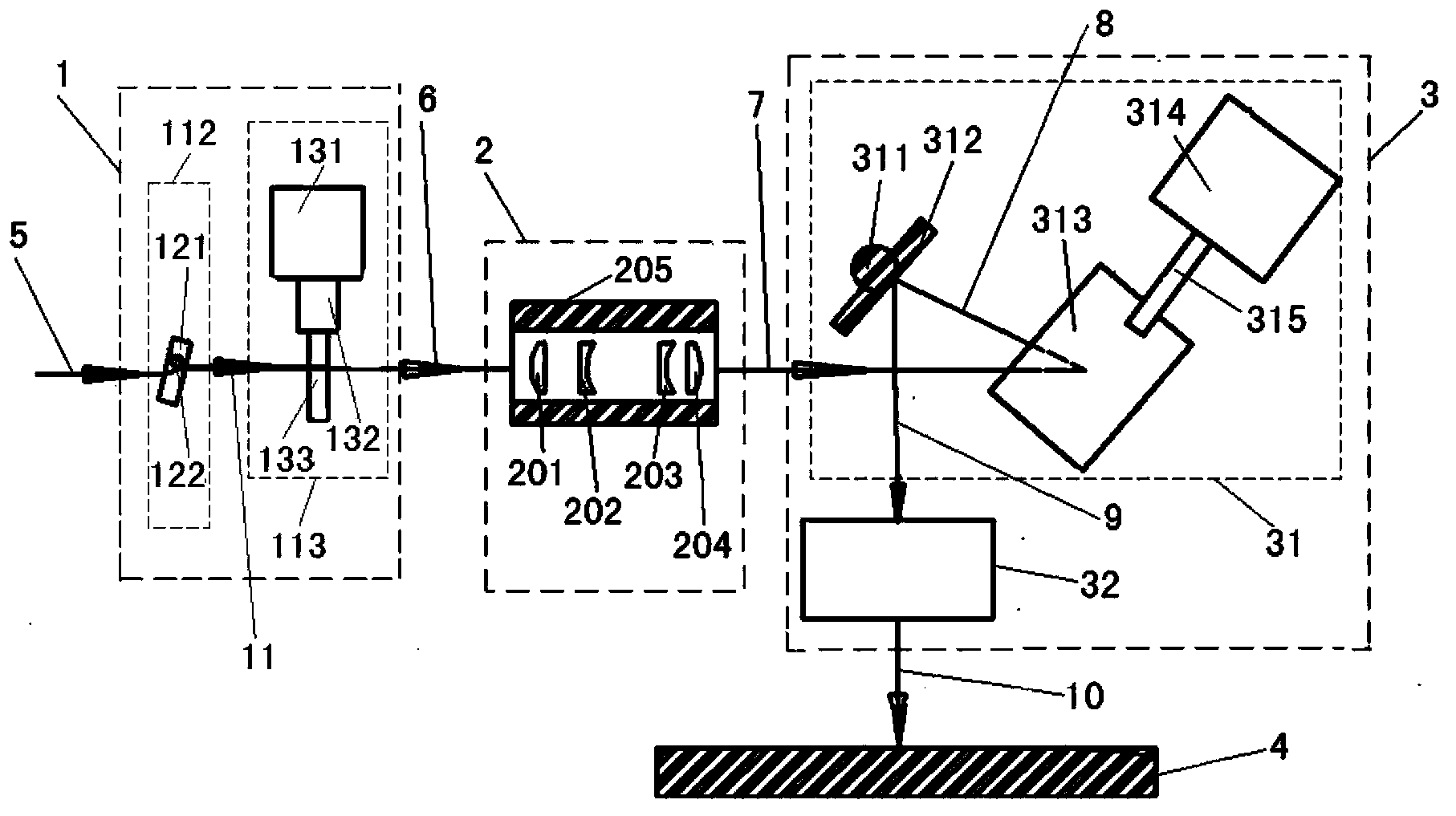
[0069] figure 2 Schematic diagram of the device structure for laser milling blind grooves of aluminum nitride ceramics, such as figure 2 As shown: the device for laser milling blind slots on aluminum nitride ceramics includes a beam transmission azimuth control module 1 , a beam trajectory imaging amplification module 2 and a laser focusing and focus switching module 3 . The structures of the beam movement trajectory imaging amplification module 2 and the laser focusing and focus switching module 3 in this embodiment are the same as those in the first embodiment.

[0070] The beam transmission azimuth control module 1 includes a beam offset modulation unit, which includes two serially connected beam offset subunits, namely a first beam offset unit 112 and a second beam offset unit 113 . The first beam shifting unit 112 includes a first flat quartz glass 121 and a first motor (not shown in the figure) for driving the first flat quartz glass 121, and the first flat quartz gla...

Embodiment 3

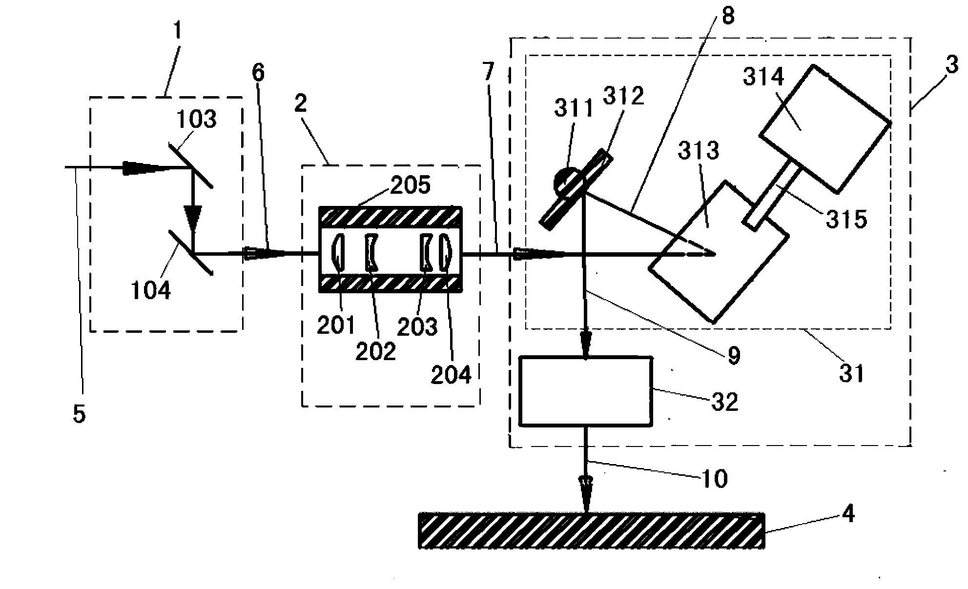
[0086] image 3 It is a schematic diagram of the device structure of embodiment 3 low-temperature co-fired ceramic laser drilling, as image 3 As shown: the device for laser drilling of low-temperature co-fired ceramics includes a beam transmission azimuth control module 1 , a beam trajectory imaging amplification module 2 and a laser focusing and focus switching module 3 . The structures of the beam movement trajectory imaging amplification module 2 and the laser focusing and focus switching module 3 in this embodiment are the same as those in the first embodiment.

[0087] The beam transmission azimuth control module 1 includes a beam offset modulation unit, which includes two series-connected beam offset subunits, namely a first beam offset unit and a second beam offset unit, the first beam offset unit The offset unit includes a first plane mirror 103 and a first piezoelectric ceramic drive system (not shown in the figure) for driving the first plane mirror 103 to move (sw...


PUM

PropertyMeasurementUnit
poweraaaaaaaaaa
frequencyaaaaaaaaaa
frequencyaaaaaaaaaa

Abstract

The invention relates to a light beam movement track control device for laser processing. The light beam movement track control device comprises a light beam transmission direction control module, a light beam movement track imaging amplification module and a light beam focusing and focus switching module, wherein the light beam transmission direction control module is used for modulating a transmission direction of an incident beam which is emitted onto the light beam transmission direction control module, the light beam movement track imaging amplification module is used for amplifying an optical axis movement track of the first light beam and performing beam expanding collimation on the first light beam to form a second light beam simultaneously, and the light beam focusing and focus switching module is used for focusing the second light beam and controlling a laser focus to switch among different processing units or performing auxiliary movement control on the laser focus within one processing unit. The light beam movement track control device has the advantages that the structure is simple, the transmission directions of the light beams can be controlled flexibly, sizes of light beam scanning movement tracks, light beam rotation radiuses and the like can be adjusted dynamically, meanwhile, scanning speeds of the laser processing light beams are accelerated, the large-size processing is facilitated, and the requirements of actual laser processing are met.

Description

technical field [0001] The invention relates to the field of laser processing, in particular to a beam movement trajectory control device for laser processing. Background technique [0002] The patent application number is 201010183539.7. The beam rotation module used cannot dynamically change the beam rotation diameter during processing. It is only suitable for the situation where the diameter of the drilling hole on the same workpiece surface changes little, so it has certain limitations. [0003] In the patent application number 200380110303.9, the circular modulation motion of the light beam in front of the vibrating mirror is a circular motion by reflecting the modulated laser light through the reflector, and the reflector is driven by piezoelectric ceramics, and its deflection range is very small, making it difficult to process larger holes. [0004] The patent application number is 201210460145.0. Since the flat optical element works in a swing mode, the range of modu...

Claims


Application Information

Patent Timeline
Patent Type & Authority Patents(China)
IPC IPC(8): B23K26/082B23K26/062B23K26/38
Inventor 张立国
Owner 张立国
Why Eureka
Try Eureka