Alternative high-throughput electroporation device

An electroporation, high-throughput technology, applied in the field of electroporation, can solve the problem of high processing cost, and achieve the effect of low cost, good heat dissipation, and automatic gene function screening

Active Publication Date: 2013-09-25
CAPITALBIO CORP +1
View PDF10 Cites 9 Cited by
  • Summary
  • Abstract
  • Description
  • Claims
  • Application Information

AI Technical Summary

Problems solved by technology

However, there are differences in the optimal electroporation conditions between different combinations of cells and transfection objects, and the device has only two electrodes, so it is impossible to simultaneously perform selective electroporation on different samples, and the processing cost is high, which limits its application

Method used


Image

  • Alternative high-throughput electroporation device
  • Alternative high-throughput electroporation device
  • Alternative high-throughput electroporation device

Examples


Embodiment 1

[0034] Embodiment 1. A high-throughput electroporation device based on a printed circuit board. The electroporation electrodes are metal parallel plates perpendicular to the substrate.

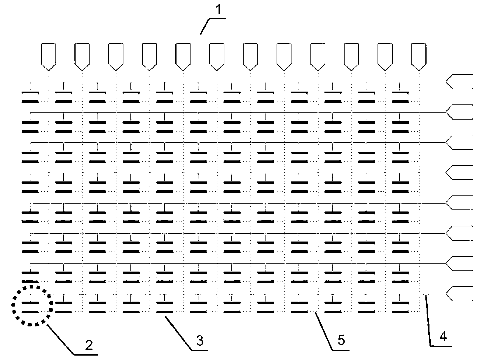
[0035] figure 1 A top view of the electroporation device provided in this example, which can be matched with a 96-well plate.

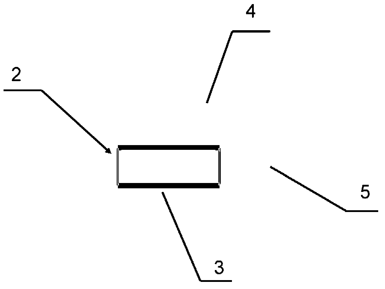
[0036] Such as figure 1 As shown, the electroporation device in this embodiment includes a substrate 1 on which 96 through holes 2 are arranged, and are matched with a 96-well plate. One electrode 3 is provided on the side wall of each through hole 2, that is, one pair of electrodes. The distance between the two electrode plates is 2mm.

[0037] In order to achieve selective control of each through hole with as few pads as possible, all electrodes on the upper side of a row of 12 holes are commonly connected to the top layer wires 4 distributed along each row on the top of the substrate 1, while all electrodes on the lower side of a row of 8 holes are connected to ...

Embodiment 2

[0044] Embodiment 2, a high-throughput electroporation device based on a printed circuit board, the electroporation electrodes are parallel to the substrate

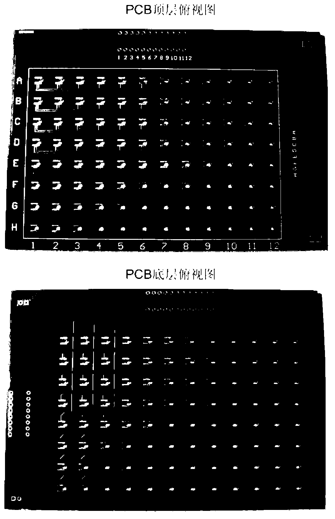
[0045] This embodiment is similar to Embodiment 1 in that the electroporation device is made of a PCB, and the difference is that this embodiment uses a circular PCB through hole to carry the electroporation system. Similar to Embodiment 1, the inside of the PCB through hole is covered with a metal layer. In order to generate the electrode pairs required for electroporation, the metal of the PCB passing through the inner wall can be milled off with a drill (such as Figure 7 shown), so that the metal layers on the top and bottom of the PCB can become electroporation electrodes. An alternative processing method is: use a drill to drill directly at the intersection of the upper and lower metal traces. As long as the diameter of the drill is smaller than the width of the metal traces, similar Figure 7 The structure shown ...

Embodiment 3

[0048] Embodiment 3. A high-throughput electroporation device based on a printed circuit board. The electroporation electrodes are metal parallel plates perpendicular to the substrate. The distance between the two electrode plates is 1mm. Its concrete experimental process is similar to embodiment 1. Compared with Example 1, the distance between electrodes is smaller, so the voltage required for electroporation is smaller.


PUM


Abstract

The invention discloses an alternative high-throughput electroporation device. The electroporation device comprises a substrate, wherein multiple through holes are formed in the substrate; a pair of electrodes is arranged at each through hole; the electrodes are connected with a wire arranged on the substrate; the electrodes can be gated in a single-point mode. The provided electroporation device can be manufactured by using a printed circuit board (PCB) manufacturing method. The electroporation device can be used for performing the electroporation on cells, such as animal cells or bacteria. During use of the device, an electroporation pulse is applied to an electroporation system in the through holes through the electrodes at the through holes. The electroporation device can be manufactured by using a PCB process, is mature in technology and low in cost and can be produced in batches. The electroporation device manufactured by using the PCB process can be seamlessly connected with a PCB-based circuit control system, and the electroporation device contributes to realizing high-throughput automatic gene function screening based on the electroporation.

Description

technical field [0001] The invention relates to a selective high-flux electroporation device, which belongs to the field of electroporation. Background technique [0002] Electroporation is a cell transfection or bacterial transformation technology that uses an external pulsed electric field to generate a transmembrane voltage on the cell membrane. When the cell transmembrane voltage exceeds a certain threshold, the cell membrane undergoes reversible perforation to introduce foreign substances into the cell. Electroporation has the advantages of no cytotoxicity, low cost, and high transfection efficiency. At present, electroporation technology has been widely used in biological research. Several types of electroporation methods exist, such as placing cells between parallel electrodes a few millimeters apart (for example, U.S. Pat. 5389069), or allowing cells to flow between parallel electrodes (for example, U.S. Pat. 6773669; Chinese patent application, publication number:...

Claims


Application Information

Patent Timeline
Patent Type & Authority Applications(China)
IPC IPC(8): C12M1/42
Inventor 徐友春苏世圣邢婉丽程京
Owner CAPITALBIO CORP
Why Eureka
Try Eureka