Multi-tube-bundle jet-fluidized anti-scale shell and tube heat exchanger using sewage and refrigerant

A shell-and-tube heat exchanger, jet flow technology, applied in the direction of heat exchanger types, indirect heat exchangers, fixed tubular conduit components, etc. It can improve the fluidization effect, strengthen heat exchange, and simplify the operation.

Inactive Publication Date: 2013-09-25
HARBIN INST OF TECH
View PDF6 Cites 12 Cited by
  • Summary
  • Abstract
  • Description
  • Claims
  • Application Information

AI Technical Summary

Problems solved by technology

[0003] The purpose of the present invention is to provide a multi-bundle jet fluidization anti-scale sewage and refrigerant shell-and-tube heat exchanger to solve the problem that the existing conventional shell-and-tube heat exchanger does not have the

Method used


Image

  • Multi-tube-bundle jet-fluidized anti-scale shell and tube heat exchanger using sewage and refrigerant

Examples


specific Embodiment approach 1

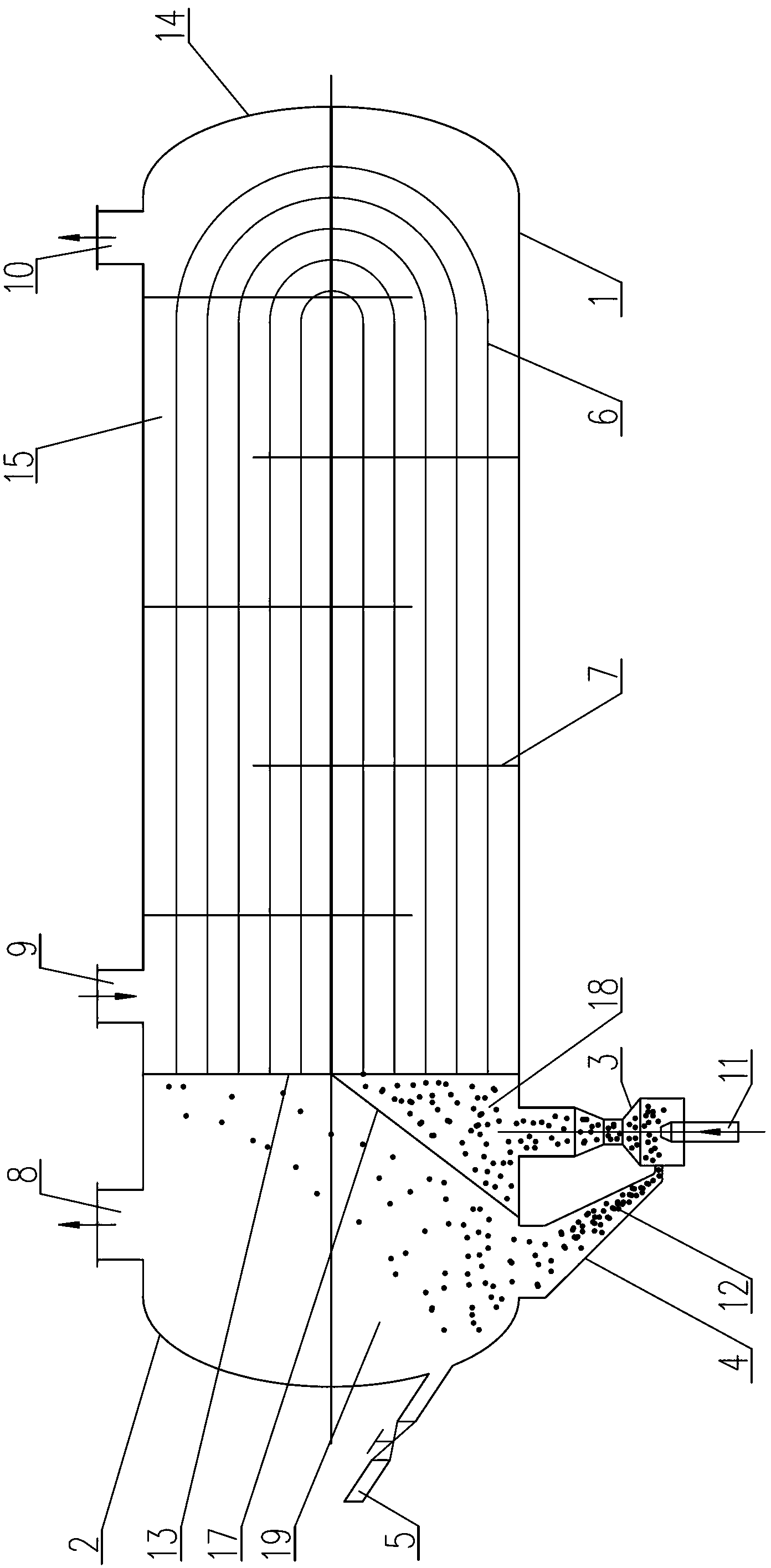
[0009] Specific implementation mode one: combine figure 1 Description, the multi-bundle jet fluidization anti-scaling sewage and refrigerant shell-and-tube heat exchanger of this embodiment, the multi-tube-bundle jet fluidization anti-scaling sewage and refrigerant shell-and-tube heat exchanger includes a shell 1, a heat exchange Tube bundle 6, solid-liquid separation end 2, distribution plate 13, head 14 and multiple baffles 7; shell 1 is placed horizontally, both ends of shell 1 are open ends, and one end of shell 1 passes through solid The liquid separation terminal 2 is closed, and the other end of the housing 1 is closed by the sealing head 14. The distribution plate 13 is arranged in the housing 1 and close to the side of the solid-liquid separation terminal 2. The inner surface of the wall is fixed, and a cavity is surrounded by the solid-liquid separation terminal 2, the shell 1 and the distribution plate 13, and a heat exchange chamber 15 is surrounded by the shell 1,...

specific Embodiment approach 2

[0010] Specific implementation mode two: combination figure 1 It is explained that the upper end of the partition plate 17 in this embodiment is arranged on the center line of the housing 1 . With this arrangement, the two ends of the multiple U-shaped heat exchange tubes in the heat exchange tube bundle 6 can be distributed on the upper and lower sides of the center line of the shell, which can improve the stability of the overall structure of the heat exchanger. The undisclosed technical features in this embodiment are the same as those in the first embodiment.

specific Embodiment approach 3

[0011] Specific implementation mode three: combination figure 1 Note that the material of the solid particles 12 in this embodiment is metal or hard plastic. Select as needed. The undisclosed technical features in this embodiment are the same as those in the first embodiment.


PUM


Abstract

The invention relates to a multi-tube-bundle jet-fluidized anti-scale shell and tube heat exchanger using sewage and refrigerant, belongs to the technical field of sewage heat exchange equipment, and solves the problems that the existing conventional shell and tube heat exchange has no functions of decontamination and scale prevention; during application of the chemical industry fluidized-bed heat exchanger in sewage, return of solid particles is unsmooth and reliable continuous descaling and heat exchange enhancement fail. Two ends of a shell are sealed through a solid-liquid separation end and a gland. A distribution plate is disposed in the shell. A cavity is enclosed by the solid-liquid separation end, the shell and the distribution plate. A heat exchange cavity is enclosed by the shell, the distribution plate and the gland. Heat exchange tube bundles are supported and fixed through the distribution plate and a plurality of baffles. The cavity is divided into a sewage inlet cavity and a solid-liquid separation cavity by a partition. Both the solid-liquid separation cavity and the sewage inlet cavity are filled with the sold particles. The upper end of the side wall of the shell is provided with a sewage outlet, a refrigerant inlet and a refrigerant outlet. An ejector is mounted at the lower end of the side wall of the shell. A solid-liquid return pipe is communicated with the solid-liquid separation cavity and the ejector. The multi-tube-bundle jet-fluidized anti-scale shell and tube heat exchanger using sewage and refrigerant is applicable to sewage heat exchange.

Description

technical field [0001] The invention belongs to the technical field of sewage heat exchange equipment, and in particular relates to a shell-and-tube heat exchanger for multi-tube bundle jet fluidization anti-scaling sewage and refrigerant. Background technique [0002] Conventional shell-and-tube heat exchangers do not have the functions of decontamination and anti-fouling. Even if the pipe diameter is increased or the baffles are reduced, the fouling can only be delayed. In addition, there are currently some sewage heat exchangers, such as dry shell-and-tube heat exchangers with fast decontamination functions, which can only be descaled periodically. However, the use of fluidized heat exchangers in chemical industry in sewage will lead to poor reflux of solid particles, and cannot reliably and continuously descale and enhance heat exchange. Contents of the invention [0003] The purpose of the present invention is to provide a multi-tube jet fluidization anti-scale sewag...

Claims


Application Information

Patent Timeline
IPC IPC(8): F28D7/06F28G1/12
Inventor 倪龙姚杨田金乙于萍
Owner HARBIN INST OF TECH
Why Eureka
Try Eureka