Current sensor for electric vehicle and detecting method by means of same

A current sensor, electric vehicle technology, applied in the direction of measuring current/voltage, instrument, measuring electricity, etc., can solve the problems of low voltage amplitude, complex circuit structure, large voltage signal interference fluctuations, etc., and achieve wide operating frequency and circuit structure Simple, wide-ranging effects

Active Publication Date: 2013-09-25
ANHUI ANKAI AUTOMOBILE
View PDF4 Cites 12 Cited by
  • Summary
  • Abstract
  • Description
  • Claims
  • Application Information

AI Technical Summary

Problems solved by technology

Since the current of the power battery system reaches hundreds of amperes during charging and discharging, and the current flows in different directions during charging and discharging, the polarity of the voltage also changes accordingly. An external voltage signal conditioning circuit is required to sample the signal. Since electric vehicles use high voltage ungrounded system, that is, the ground loop of the high-voltage system and the chassis of the vehicle body is an insulating loop, and the voltage sampling circuit and the vehicle body ground need to be isolated, and then differential sampling is performed, and the circuit structure is complex
The conditioned voltage signal is disturbed and fluctuates greatly during the transmission process
[0006] In addition, the resistance method detects the power supply by measuring the voltage on the shunt to estimate the current flowing through the system. Since the resistance of the shunt is small, the sampled voltage amplitude is low, and an external signal amplification circuit is required, and the measurement circuit is in harmony with the high-voltage system. Direct connection, the circuit needs secondary isolation

Method used


Image

  • Current sensor for electric vehicle and detecting method by means of same
  • Current sensor for electric vehicle and detecting method by means of same

Examples


Embodiment Construction

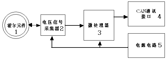
[0032] Such as figure 1 As shown, a current sensor for an electric vehicle includes a Hall element 1, and the Hall element 1 is electrically connected to a voltage signal collector 2 in an interactive manner, and the output terminal of the voltage signal collector 2 is connected to a microprocessor 3 The input end of the microprocessor 3 and the voltage signal collector 2 are both provided with working power by the power supply circuit 5; the output end of the microprocessor 3 is connected with a CAN communication interface 4 for communicating with an external network.

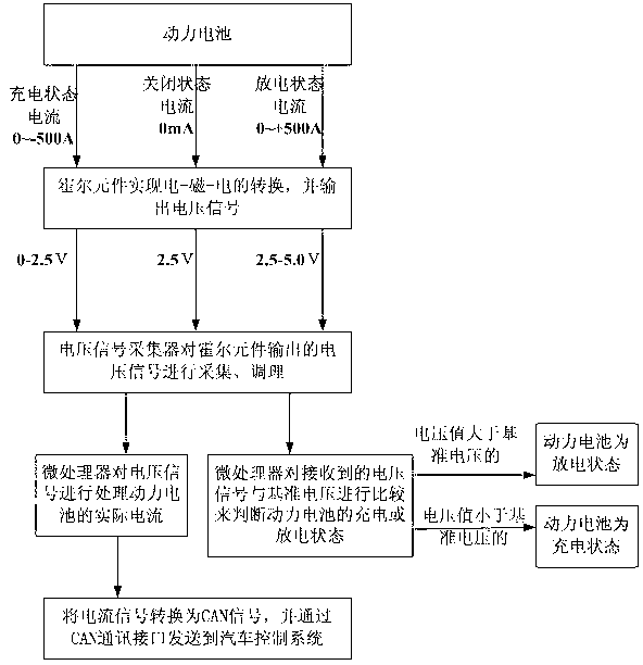
[0033] Such as figure 2 Shown, a kind of detection method of electric vehicle current sensor comprises the following steps:

[0034] (1) Pass the wire of the electric vehicle power battery through the magnetic ring of the Hall element, and the Hall element realizes the conversion of electricity-magnetism-electricity;

[0035] (2) The magnetic field strength of the Hall element changes accordingly with the c...


PUM


Abstract

The invention provides a current sensor for an electric vehicle. The current sensor comprises a Hall element. The Hall element is electrically connected with a voltage signal collector in an interactive mode, the output end of the voltage signal collector is connected with the input end of a microprocessor, and the working power of the microprocessor and the working power of the voltage signal collector are both provided by a power circuit. The invention further provides a method for detecting currents of a power battery by means of the current sensor. According to the current sensor and the detecting by means of the current sensor, the Hall element is adopted to produce a magnetic field around an energized conductor, wherein the magnetic field is in direct proportion to the currents of the power battery, the currents of the current-carrying conductor are indirectly measured through the method of measuring Hall potentials, and therefore the purposes of detecting the total currents of the power battery and charging and discharging states of the power battery are achieved. The processing amount of the microprocessor is reduced, the circuit structure is simple, interference to voltage signals is small, and a detected value is relatively precise.

Description

[0001] technical field [0002] The invention relates to the technical field of electric vehicles, in particular to a current sensor for detecting charging and discharging current of a power battery system of an electric vehicle and a detection method thereof. [0003] Background technique [0004] The main working principle of the new energy electric vehicle is to provide electric energy to the motor through the lithium battery to drive the motor to run, thereby propelling the car forward. As the power device of an electric vehicle, a plurality of single lithium batteries are connected in series and in parallel to form a high-power and large-capacity lithium battery pack. The charging and discharging performance of lithium batteries directly affects the overall performance and driving mileage of electric vehicles. The electric vehicle control system has many monitoring and control units, all of which need to sample the total current of the battery system and carry out cor...

Claims


Application Information

Patent Timeline
Patent Type & Authority Applications(China)
IPC IPC(8): G01R19/00G01R31/36
Inventor 吴成加洪洋熊良平陈顺东丁传记李韧周保成唐伟
Owner ANHUI ANKAI AUTOMOBILE
Why Eureka
Try Eureka