Hydraulic billet shears

A technology for hydraulic shears and billets, applied in the field of hydraulic shears for billets, can solve the problems of inability to work in a high temperature environment for a long time, difficult to disassemble and maintain, low production efficiency, etc. high effect

Active Publication Date: 2015-05-27
FUZHOU KANGFUTE MACHINERY & EQUIP
View PDF6 Cites 1 Cited by
  • Summary
  • Abstract
  • Description
  • Claims
  • Application Information

AI Technical Summary

Problems solved by technology

[0003] The invention proposes a billet hydraulic shear, which solves the defects in the prior art such as deformation of the cutting head, inability to work in a high temperature environment for a long time, high cost, low production efficiency, and difficult disassembly and maintenance.

Method used


Image

  • Hydraulic billet shears
  • Hydraulic billet shears
  • Hydraulic billet shears

Examples


Embodiment Construction

[0027] The following will clearly and completely describe the technical solutions in the embodiments of the present invention with reference to the accompanying drawings in the embodiments of the present invention. Obviously, the described embodiments are only some, not all, embodiments of the present invention. Based on the embodiments of the present invention, all other embodiments obtained by persons of ordinary skill in the art without making creative efforts belong to the protection scope of the present invention.

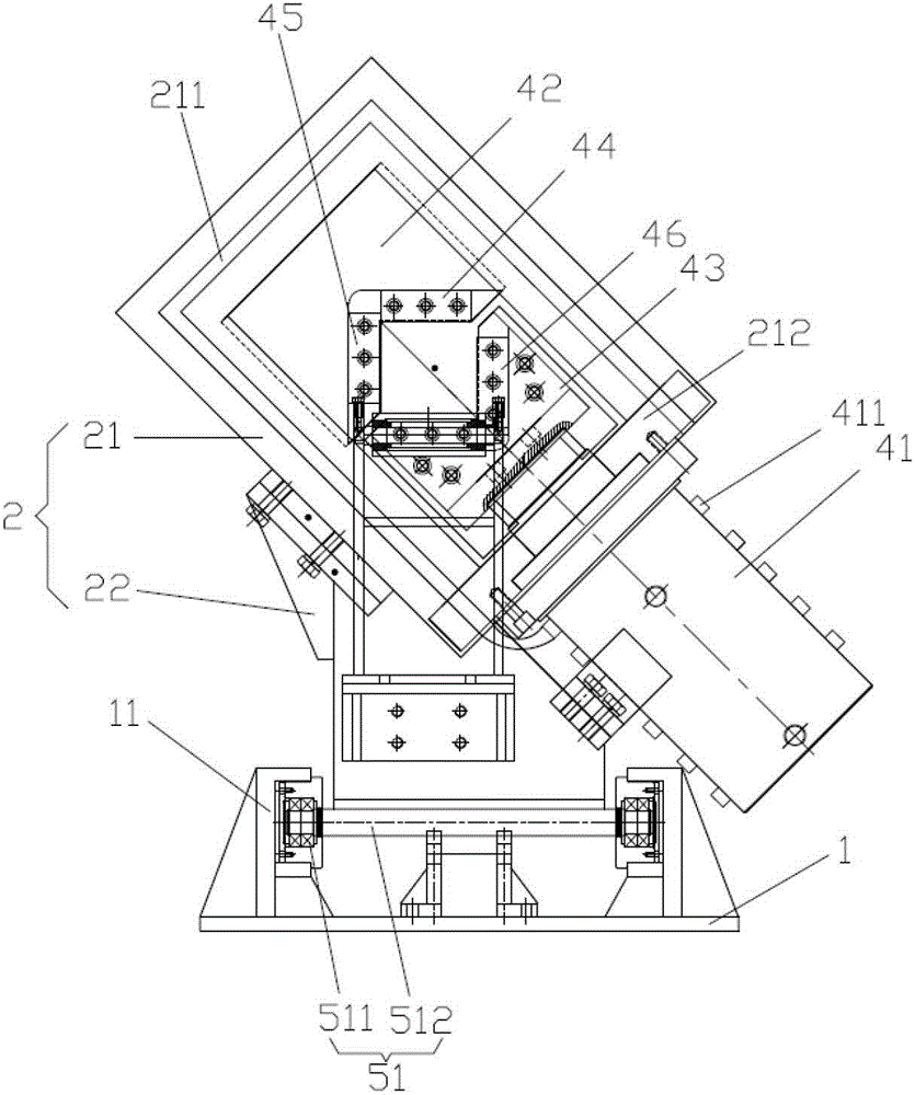
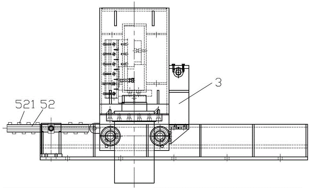
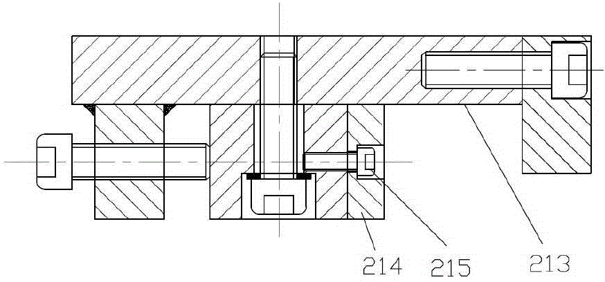
[0028] refer to Figure 1-3 , a steel billet hydraulic shear, including a base 1, a frame 2, a shearing device (not shown), a traveling device (not shown), a hydraulic station (not shown) and a control host (not shown), its features That is, the frame 2 includes a shearing slant frame 21 and a support frame 22, and the shearing slant frame 21 is composed of a left slash (not shown), a right slash (not shown), an upper slant beam (not shown) shown) and the she...


PUM


Abstract

The invention provides a pair of hydraulic billet shears which comprises a base, a rack, a shear device, a running mechanism, a hydraulic station and a control host, wherein a roller supporting device is fixed on a support bracket; a shear oblique frame is internally provided with an internal cooling water channel; a travel switch is arranged on the shear oblique frame; a shear oil cylinder is fixed on a shear oil cylinder fixing bar and the support bracket and fixedly connected with a lower knife seat; a shear oil cylinder housing is provided with a spiral first external cooling water channel; the first external cooling water channel is connected with the internal cooling water channel; a running oil cylinder is fixed on the base and fixedly connected with the support bracket; a running oil cylinder housing is provided with a spiral second external cooling water channel; and wheels are arranged in adjustable U-shaped grooves in guide rails in an embedded manner. The pair of shears is high in cutoff speed, low in equipment failure, high in blade utilization ratio and production efficiency and low in energy consumption, and sheared end faces are square and tidy.

Description

technical field [0001] The invention relates to the field of billet cutting equipment, in particular to a billet hydraulic shear. Background technique [0002] The current steel production technology generally adopts continuous steel casting technology, which requires that the steel billet must be cut to a fixed length when it comes off the assembly line, and the cut head should be square without deformation. Currently, flame cutting is generally used to cut steel billets, but when flame cutting, steel billets will have a certain amount of fixed cutting consumption and oxygen acetylene consumption, and the cost is high. Existing cutting machines have various defects, such as being unable to work in a high-temperature environment for a long time, high in cost, low in production efficiency, difficult to disassemble and maintain, and severely deformed and bent at the cutting head, which affects post-processing. Contents of the invention [0003] The invention proposes a stee...

Claims


Application Information

Patent Timeline
Patent Type & Authority Patents(China)
IPC IPC(8): B23D15/14B23D35/00B23D33/00
Inventor 孙平
Owner FUZHOU KANGFUTE MACHINERY & EQUIP
Why Eureka
Try Eureka