Ratio fringe counting method and displacement sensor demodulation system based on double f-p interferometer

A fringe counting and F-P technology, applied in instruments, measuring devices, optical devices, etc., can solve the problems of low system accuracy and the inability of fiber end face processing technology to meet the accuracy requirements, and achieve the effect of reducing complexity

Active Publication Date: 2016-07-06
WUHAN UNIV OF TECH
View PDF4 Cites 0 Cited by
  • Summary
  • Abstract
  • Description
  • Claims
  • Application Information

AI Technical Summary

Problems solved by technology

However, the current optical fiber end-face processing technology cannot meet this precision requirement.
Tong Bin of Wuhan University of Technology and others proposed a dual-fiber F-P structure based on random phase difference, focusing on solving the problem of stripe direction judgment, but this method has two defects: first, the type of sensing unit needs to be determined in advance, and second, the judgment needs to be dynamically changed Threshold to eliminate the influence of light intensity attenuation caused by the increase of cavity length, so the system accuracy is not high

Method used


Image

  • Ratio fringe counting method and displacement sensor demodulation system based on double f-p interferometer
  • Ratio fringe counting method and displacement sensor demodulation system based on double f-p interferometer
  • Ratio fringe counting method and displacement sensor demodulation system based on double f-p interferometer

Examples


Embodiment Construction

[0041] The technical solutions of the present invention will be further described below in conjunction with the embodiments and the accompanying drawings.

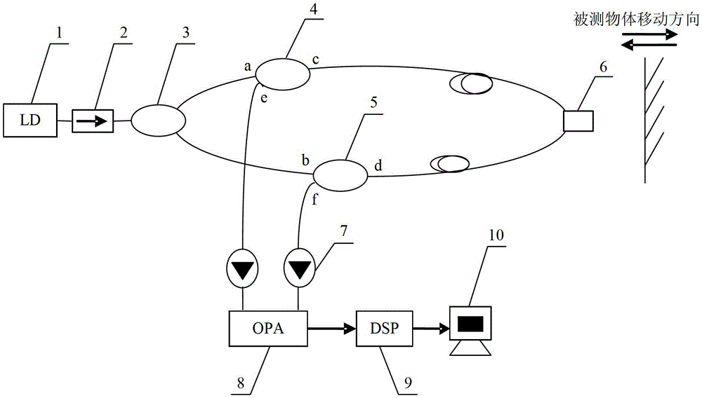
[0042] refer to Figure 1 ~ Figure 2 As shown, the displacement sensor demodulation system based on the ratio fringe counting method of the double F-P interferometer according to the present invention includes a laser 1, a fiber isolator 2, a first fiber coupler 3, a second fiber coupler 4, a third Optical fiber coupler 5, sensing unit 6, photodetector 7, preamplification unit 8, DSP signal processing module 9 and peripheral display unit 10, the output end of described laser 1 is connected with the input port of optical fiber isolator 2, The output port of the fiber isolator 2 is connected with the input end of the first fiber coupler 1, and the output port of the first fiber coupler 1 is respectively connected with the input port a of the second fiber coupler 2 and the input port of the third fiber coupler 3 b is connect...


PUM


Abstract

The invention provides a ratio fringe counting method based on a dual F-P (Fabry-Perot) interferometer and a displacement sensor demodulating system. Two interference optical intensity signals are divided directly; an obtained ratio generates positive and negative pulses during a cavity length changing process of an F-P cavity after direct current items are eliminated; the increase or decrease of the F-P cavity length is judged according to the positive and negative of the pulses; and a counter counts two times when an optical path difference is changed by a wavelength. The corresponding displacement sensor demodulating system comprises a laser device, an optical fiber isolator, a first optical fiber coupler, a second optical fiber coupler, a third optical fiber coupler, a sensing unit, photoelectric detectors, a pre-amplification unit, a DSP (Digital Signal Processing) module and a peripheral display unit. The method and the system have the following benefits that sensor type calibration, operation and orientation-judgment processes are removed; the complexity of a demodulating algorithm is reduced; the theory precision of the ratio fringe counting method is two times the precision of the general fringe counting method; and due to a congenital anti-interference capacity, the miniaturization of a measurement instrument is realized by the DSP module.

Description

technical field [0001] The invention relates to a method and a device for dynamic phase demodulation of an optical fiber displacement sensor, in particular to a ratio fringe counting method based on a double F-P interferometer and a displacement sensor demodulation system. Background technique [0002] F-P interferometric optical fiber sensor has the advantages of high measurement accuracy, single-ended detection and simple optical path, and has broad application prospects (such as pressure detection of dams and bridges, safety detection of large machinery, petroleum and military fields). The signal extraction of the fiber optic F-P sensor can adopt two methods of intensity demodulation or phase demodulation. The phase demodulation method is accurate, but relatively complicated and costly; the intensity demodulation method, such as the fringe counting method, has a certain advantage because of its simple principle and low cost. However, at the extreme value (peak or trough)...

Claims


Application Information

Patent Timeline
Patent Type & Authority Patents(China)
IPC IPC(8): G01B11/02
Inventor 黎敏舒卓徐春晖
Owner WUHAN UNIV OF TECH
Why Eureka
Try Eureka