Supercharge Your Innovation With Domain-Expert AI Agents!

Double Action Electromagnetic Release

An electromagnetic release, double-action technology, applied in the direction of the protection switch operation/release mechanism, etc., can solve the problems of reducing the cost of the electromagnetic release, reducing the volume of the electromagnetic release, and unreliable residual current protection.

Active Publication Date: 2015-11-18
ZHEJIANG CHINT ELECTRIC CO LTD
View PDF6 Cites 0 Cited by
  • Summary
  • Abstract
  • Description
  • Claims
  • Application Information

AI Technical Summary

Problems solved by technology

[0004] The present invention solves these problems and provides a double-action electromagnetic tripper, which can greatly reduce the spring reaction force overcome by the residual current tripping action, and solves the problems existing in the existing double-action electromagnetic tripper at low voltage. The unreliable problem of residual current protection and the problem of high voltage impact make the working voltage of the voltage coil drop from hundreds of volts to tens of volts (such as low voltage of 50V level), so that electromagnetic trippers with different rated currents can be used The same voltage coil and residual current tripping control circuit not only makes the structure of the electromagnetic tripper simpler and more reasonable, but also omits the yoke in the magnetic circuit of the voltage coil and the device for resisting high voltage shocks in the residual current tripping control circuit , reduce the cost of the electromagnetic tripper, significantly reduce the volume of the electromagnetic tripper, make full use of the space of the distribution box, and effectively overcome the problem of magnetic flux leakage, and work reliably

Method used


Image

  • Double Action Electromagnetic Release
  • Double Action Electromagnetic Release
  • Double Action Electromagnetic Release

Examples


Embodiment Construction

[0021] The following in conjunction with the attached for example purposes only Figures 1 to 6 , to further illustrate the specific implementation of the double-action electromagnetic tripper of the present invention, so that other advantages and features of the present invention will become easier to understand through the detailed description.

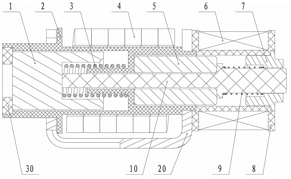
[0022] figure 1 The schematic plan view of the overall structure shows that the first skeleton 2 arranged in the yoke 20, the current coil 4 installed on the coil skeleton, the second skeleton 8 and the voltage coil 6 installed on the coil skeleton, the first The double-action electromagnetic release of the present invention composed of a moving iron core 1, a second moving iron core 5, a static iron core 7, a first reaction force spring 3, a second reaction force spring 9, a push rod 10 and a cover plate, The electromagnetic release adopts two independent reaction force spring structures and two independent magnetic circuit dockin...


PUM


Abstract

The invention provides a double-action electromagnetic trip. The head of an ejector rod is glidingly mounted in a first bearing hole of a static iron core and stretches out of the hole; a first framework is sleeved with a current coil and arranged in a magnetic yoke, and accommodates a first reaction spring and a first movable iron core; two ends of the first reaction spring abut against a first spring accommodating hole of the first movable iron core and a support of the first framework respectively; the first movable iron core is contacted and matched with an association operation end of the tail part of the ejector rod; and under the action of short circuit of the current coil, a current magnetic field drives to prevent the elastic force of the first reaction spring from pushing the ejector rod to move. A second framework is sleeved with a voltage coil and accommodates a second reaction spring and a static iron core; two ends of the second reaction spring are connected with a limit step of the ejector rod and the static iron core respectively; a second movable iron core is mounted in an accommodating area formed through butt joint of the two frameworks through a linear sliding pair structure and is contacted and matched with a limit step of the ejector rod, and under the action of short circuit of the voltage coil, a current magnetic field drives to push the ejector rod to prevent the second reaction spring from moving.

Description

technical field [0001] The invention relates to an electromagnetic tripper, which is mainly used in a modular small residual current action circuit breaker, and has the functions of residual current, short circuit and overload protection. Background technique [0002] The residual current operated circuit breaker has two sets of electromagnetic releases that can generate tripping action, one of which is a short-circuit instantaneous release, and the other is a residual current release. The former is a current-type electromagnetic release. The latter is a voltage-type electromagnetic release. These two sets of electromagnetic releases need to take up a lot of space, so that the volume of a single circuit breaker is larger, and the larger the space it occupies in the distribution box, the less the number of circuit breakers that the distribution box can accommodate. For this reason, for small residual current operated circuit breakers used in circuits with a rated current up ...

Claims


Application Information

Patent Timeline
Patent Type & Authority Patents(China)
IPC IPC(8): H01H71/24
Inventor 潘友义
Owner ZHEJIANG CHINT ELECTRIC CO LTD
Features
  • R&D
  • Intellectual Property
  • Life Sciences
  • Materials
  • Tech Scout
  • Unparalleled Data Quality
  • Higher Quality Content
  • 60% Fewer Hallucinations
Learn More