
Multi-frequency microstrip patch antenna

A microstrip patch antenna and microstrip technology, applied in the field of mobile communication system and wireless communication, can solve the problems of limited application range, poor radiation characteristics, complex antenna structure, etc., and achieve cross-polarization characteristics and good radiation pattern, The effect of high gain and simple structure

Inactive Publication Date: 2013-10-02
JIANGSU UNIV
View PDF2 Cites 1 Cited by
  • Summary
  • Abstract
  • Description
  • Claims
  • Application Information

AI Technical Summary

Problems solved by technology

But they can only be applied to a single communication system, and some antennas that can be applied to both WLAN and WIMAX systems have also been proposed, but the complex structure or large size of these antennas is not conducive to the integration of printed antennas, and the radiation characteristics are not good. Its scope of application is limited

Method used


Image

  • Multi-frequency microstrip patch antenna
  • Multi-frequency microstrip patch antenna
  • Multi-frequency microstrip patch antenna

Examples


Embodiment Construction

[0016] The present invention will be further described below in conjunction with the accompanying drawings and embodiments.

[0017] The basic idea of ​​the invention is to realize the characteristics of simple structure and multi-frequency of the antenna by using slots of a specific shape on the patch.

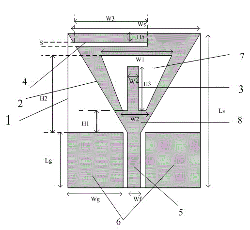
[0018] figure 1 Main view for this design. The multi-frequency microstrip patch antenna of this design includes a microstrip dielectric substrate 1, a main radiation unit 8 located on the upper surface of the microstrip dielectric substrate 1, an impedance matching input transmission feeder 5, and two rectangular metal radiation plates 6, and is characterized in that: The length of the microstrip dielectric substrate (1) is adjustable in the range of 47-48mm, and the width is adjustable in the range of 43-44mm. The shape of the main radiation unit 8 is on the triangular patch 2, and the distance from the upper edge of the triangular patch 2 Within the range of 1-1.5mm, a r...


PUM


Abstract

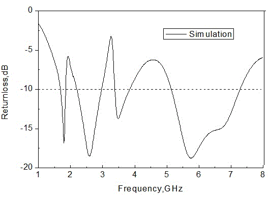
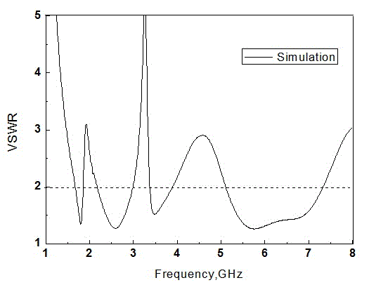
The invention discloses a multi-frequency microstrip patch antenna. The requirements are satisfied through slotting a triangular patch and arranging a radiation patch. The AnsoftHFSS software simulation result shows that four stopbands are formed in the frequency bands of 1.69-1.89 GHz, 2.13-2.97 GHz, 3.39-3.94 GHz and 5.09-7.23 GHz. The multi-frequency microstrip patch antenna has the characteristics of simple structure, small size, light weight, low profile, low cost, easiness in integration and batch processing, and the like, displays favorable radiation direction property within the whole working frequency band range, and can be widely used in mobile communication, a wireless local area network, a worldwide interoperability for microwave access network, a Bluetooth system and the like.

Description

technical field [0001] The invention belongs to the field of mobile communication systems and wireless communication, in particular to a four-band microstrip patch antenna. Background technique [0002] With the rapid development of modern communication systems and electronic technology, the volume of various communication equipment is continuously reduced, and the communication frequency band is constantly developing to wide-band and high-frequency bands. The requirements for communication equipment are also becoming higher and higher, thus promoting the development of The development of antennas, one of the key components of communication systems. Microstrip antenna, as a new type of antenna successfully researched in the 1970s, has been widely used in radio astronomy, satellites due to its low profile, small size, light weight, easy integration with microwave integrated circuit processing, and easy miniaturization. Communications and UWB and other modern communications. ...

Claims


Application Information

Patent Timeline
Patent Type & Authority Applications(China)
IPC IPC(8): H01Q1/38H01Q5/00H01Q13/08H01Q5/20H01Q5/335
Inventor 杨利霞王吉利施卫东石斌夏景
Owner JIANGSU UNIV
Learn More