
Artificial external chest compression machine

A manual, bar-pressing technology, applied in the direction of iron lungs, etc., can solve the problems that affect the treatment effect, the rescuer cannot guarantee the standard pressing operation, and the equipment cannot be used, so as to achieve the effect of labor-saving operation, less fatigue, and less damage.

Inactive Publication Date: 2013-10-09
张强
View PDF6 Cites 5 Cited by
  • Summary
  • Abstract
  • Description
  • Claims
  • Application Information

AI Technical Summary

Problems solved by technology

Manual unarmed chest compressions usually cannot meet the requirements of uninterrupted chest compressions, and the rescuer cannot guarantee the standard compression operation after fatigue, which affects the treatment effect; when using equipment to perform compression treatment, it is usually limited by the operating environment. The device cannot be used if it is removed from the power source or if the backup power source is insufficient

Method used


Image

  • Artificial external chest compression machine
  • Artificial external chest compression machine
  • Artificial external chest compression machine

Examples


Embodiment Construction

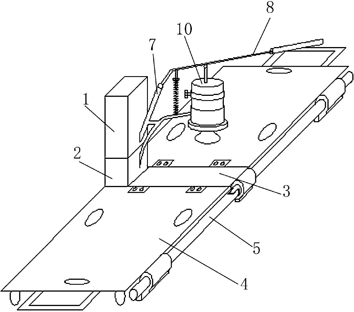
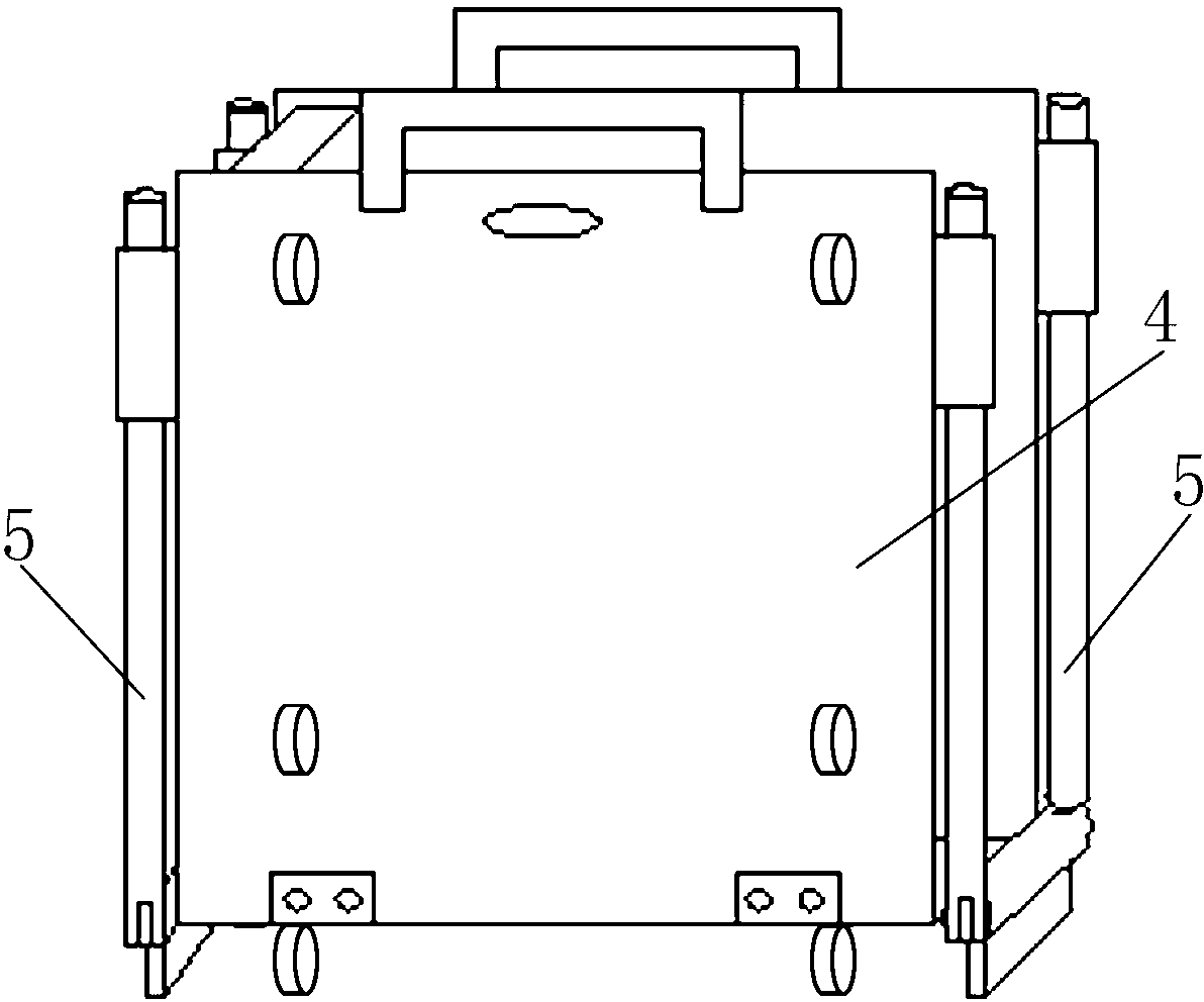
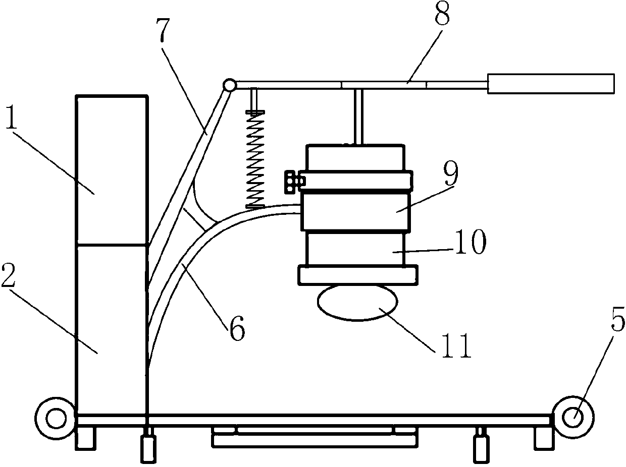
[0011] The present invention will be further described now in conjunction with accompanying drawing, figure 1 It is an embodiment of the present invention, mainly including a support frame and a pressing device, the support frame includes a column 1, an outer sleeve 2 and a base 3, etc., the base 3 is a rectangular plate arranged horizontally, and the column 1 is arranged on the base 3 On the upper part of one end, the column 1 is a vertical column, usually a square column, that is, a column with a rectangular cross section. The column 1 and the base 3 form an L-shaped structure perpendicular to each other. The inner hole of the outer sleeve 2 matches the column 1 and is sleeved on the outside of the column 1. The outer sleeve 2 can move up and down along the column 1, but cannot rotate. The outer sleeve 2 is fastened to the column 1 by bolts. Both sides of the base 3 are provided with hinged supporting plates 4, the bottom of the base 3 and each supporting plate 4 are evenly...


PUM


Abstract

The invention relates to the technical field of medical equipment, in particular to an artificial external chest compression machine used for saving a patient through cardio-pulmonary resuscitation. The artificial external chest compression machine comprises a supporting frame and a compression device. The supporting frame comprises an upright column, an outer sleeve and a base. The base is a rectangular plate which is arranged transversely. The upright column is arranged on the upper portion of one end of the base. The outer sleeve is arranged on the outer side of the upright column in a sleeved mode. Two sides of the base are provided with supporting plates respectively, wherein the supporting plates are in hinge joint. Masts are arranged on two sides of each supporting plate. The compression device comprises a lower supporting rod, an upper supporting rod, a pressing rod, a fixing sleeve, an anchor peg, a pressing depth limiting ring and a pressing block. The lower supporting rod is located below the upper supporting rod. The upper end of the upper supporting rod is connected with the pressing rod. The upper end of the lower supporting rod is fixedly connected with the fixing sleeve. The anchor peg is inserted in the fixing sleeve. A reset limiting disc and the pressing block are arranged at the lower end of the anchor peg. A spring is arranged between the pressing rod and the lower supporting rod. The artificial external chest compression machine has the advantages of being reasonable and simple in structure, simple and convenient to operate, free from restriction of a power supply in use, and capable of transferring the patient while saving the patient continuously.

Description

[0001] technical field [0002] The invention relates to the technical field of medical equipment, in particular to an artificial chest compression machine for cardiopulmonary resuscitation patients. Background technique [0003] Chest compressions are an important part of cardiopulmonary resuscitation (CPR) technique. Experts from various countries have the following consensus on chest compressions: (1) In order to ensure the blood perfusion of tissues and organs during CPR, effective chest compressions must be implemented. (2) Effective chest compressions must be fast and powerful. The compression depth for adults is 4-5cm. (3) Try to avoid interruption of chest compressions. Effective compression requires the rescuer to straighten the elbows, keep the upper limbs in a straight line, and keep the shoulders facing the hands, causing the body to lean forward. Such a posture and position make the rescuer extremely fatigued, difficult to master the depth and frequency of com...

Claims


Application Information

Patent Timeline
Patent Type & Authority Applications(China)
IPC IPC(8): A61H31/02
Inventor 张强张舵付克兰马萍
Owner 张强
Learn More