Selective-failure-based 3D (three-dimensional) printing method for preparing mold

A 3D printing and selective technology, applied in the field of 3D printing, can solve the problems of difficult to improve the performance of molded parts, low surface finish, high temperature resistance, etc., to achieve the effect of improving molding speed and efficiency, high dimensional accuracy requirements, and protecting details.

Inactive Publication Date: 2013-10-09
DALIAN UNIV OF TECH
View PDF4 Cites 14 Cited by
  • Summary
  • Abstract
  • Description
  • Claims
  • Application Information

AI Technical Summary

Problems solved by technology

[0012] SLS method: It is necessary to sinter the molding area of ​​each layer, which makes the molding time longer; molded parts generally have problems such as poor dimensional accuracy and low surface finish
[0013] LOM method: The range of material selection is relatively narrow. Generally, only continuous thin materials such as paper can be used. It is difficult to improve the performance of molded parts, and it is not resistant t

Method used


Image

  • Selective-failure-based 3D (three-dimensional) printing method for preparing mold
  • Selective-failure-based 3D (three-dimensional) printing method for preparing mold
  • Selective-failure-based 3D (three-dimensional) printing method for preparing mold

Examples


Embodiment 1

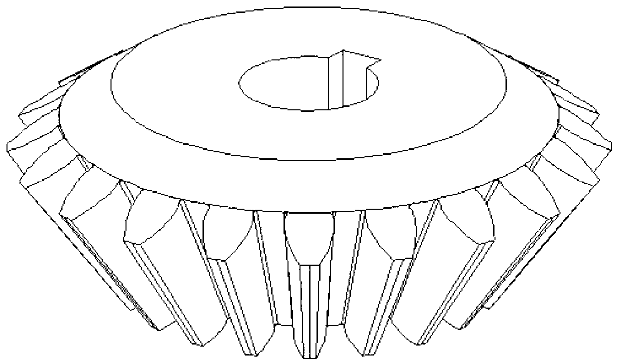
[0031] Example 1: 3D printing of "straight bevel gear" mold, using laser selective failure method

[0032] Firstly, draw the 3D CAD solid model of the "straight bevel gear" casting, and process it with the computer to get the 3D CAD solid model of the "straight bevel gear" casting mold. The casting corresponds to the cavity inside the mold, forming a "straight bevel gear" Toothed bevel gear" casting - 3D CAD solid model of the casting mold.

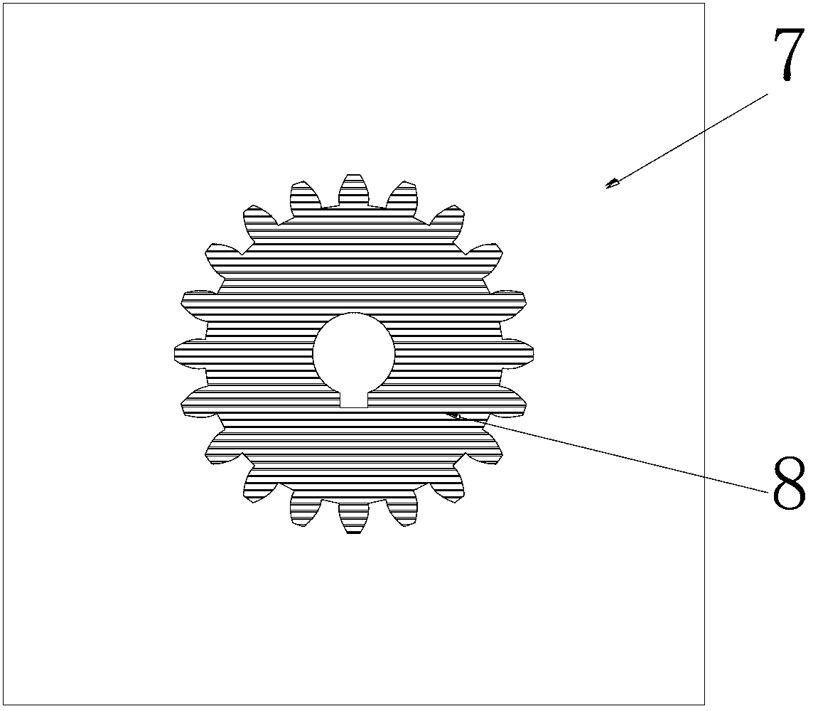
[0033] Then, the above-mentioned solid model is sliced ​​in layers in the Z direction, and the slice thickness is 0.3 mm, and each layer slice generates a casting-mold boundary contour line. The part corresponding to the outside of the contour line is the "straight bevel gear casting", and the part corresponding to the contour line and the inside of the contour line is the "straight bevel gear casting". This part is the area that needs selective failure processing.

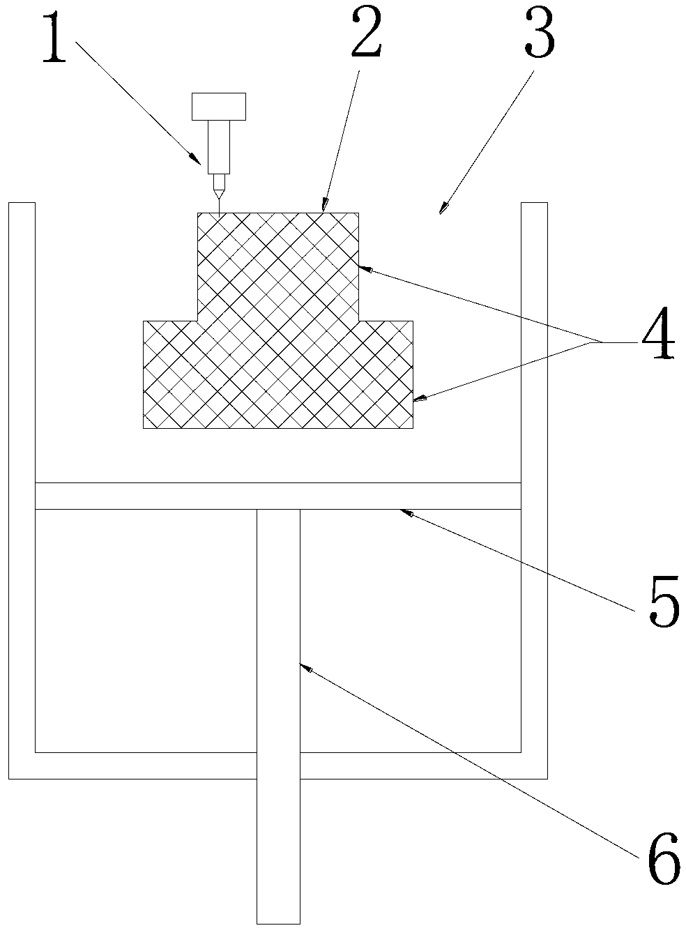
[0034] Then, the 3D printer control system starts to lay the coated san...

Embodiment 2

[0037] Example 2: 3D printing of the "cam" mold, using a laser selective failure method

[0038] First, draw the 3D CAD solid model of the "cam" casting, and the computer will process it to get the 3D CAD solid model of the "cam" casting mold. The casting corresponds to the cavity inside the casting mold to form a "cam" casting - mold 3D CAD solid model.

[0039] Then, the above-mentioned solid model is sliced ​​in layers in the Z direction, and the slice thickness is 0.3 mm, and each layer slice generates a casting-mold boundary contour line. The part corresponding to the outside of the contour line is the "cam casting mold", and the part corresponding to the contour line and the inside of the contour line is the "cam casting part". This part is the area that needs selective failure processing.

[0040] Then, the 3D printer control system starts to process the coated sand powder body. According to the boundary contour line of the casting-mold of each slice, the computer cont...


PUM


Abstract

The invention relates to a selective-failure-based 3D (three-dimensional) printing method for preparing a mold, and belongs to the technical field of 3D printing. The method comprises the following steps of: drawing three-dimensional CAD solid models of a casting and the mold; carrying out hierarchical slicing along the Z direction to form a boundary contour line of the casting-mold of each layer of slice; carrying out full region failure on powder of the contour line and the inner side of the contour line, or carrying out the full region failure on the corresponding part of the casting or forming a series of fragments which are intersected with one another and easily stripped by using a different-angle crosshatch selective failure method; after completion of hierarchical processing, carrying out the post-treatment enhancement on the powder, and the overall consolidation on the corresponding part of the mold; carrying out the full region failure on the corresponding part of the casting or forming easily stripped fragments, and removing by exerting the appropriate external force and other methods to form the mold. The method provided by the invention has the effects and benefits that the molding speed and efficiency are greatly improved when the mold is prepared, a failure region is conveniently removed, the details of the mold are effectively protected, and the molds with high dimensional accuracy requirements and complex shapes can be prepared.

Description

technical field [0001] The invention belongs to the technical field of 3D printing, and relates to a method for realizing the digital production of casting moulds, based on the 3D printing technology. Background technique [0002] 3D printing (3D printing), a kind of rapid prototyping technology, the principle is to decompose the three-dimensional model designed by the computer into several layers of plane slices, and then superimpose the "printed" materials layer by layer according to the slice graphics, and finally "stack" into a complete object. [0003] At present, 3D printing technologies mainly include SLA, FDM, SLS, LOM, etc. [0004] Stereolithography (SLA): also known as stereolithography or stereolithography, is the earliest developed rapid prototyping technology. It uses photosensitive resin as the raw material, and controls the ultraviolet laser through the computer to scan the surface of the photosensitive resin point by point according to the information of e...

Claims


Application Information

Patent Timeline
IPC IPC(8): B22C9/00
Inventor 姚山王廷利姚平坤
Owner DALIAN UNIV OF TECH
Why Eureka
Try Eureka