Pneumatic drier with tail gas waste heat recycling function

A technology of airflow dryer and waste heat recovery, applied in dryers, drying gas layout, drying and other directions, can solve problems such as heat energy waste, and achieve the effects of reducing waste, good low temperature performance, good economic benefits and environmental benefits

Inactive Publication Date: 2013-10-09
江苏格兰特干燥浓缩设备有限公司
View PDF6 Cites 9 Cited by
  • Summary
  • Abstract
  • Description
  • Claims
  • Application Information

AI Technical Summary

Problems solved by technology

The hot and humid steam discharged to the atmosphere contains a large amount of calorific value. Direct discharge to the atmosphere is not only a waste of heat energy, but also has a little impact on the surrounding environment, which needs to be improved

Method used


Image

  • Pneumatic drier with tail gas waste heat recycling function
  • Pneumatic drier with tail gas waste heat recycling function
  • Pneumatic drier with tail gas waste heat recycling function

Examples


Embodiment Construction

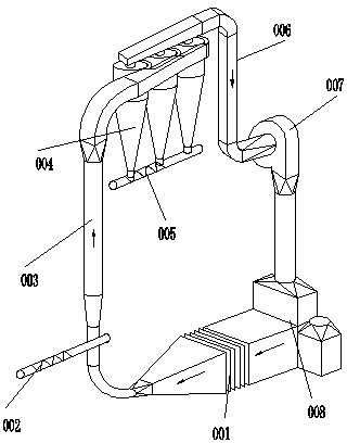
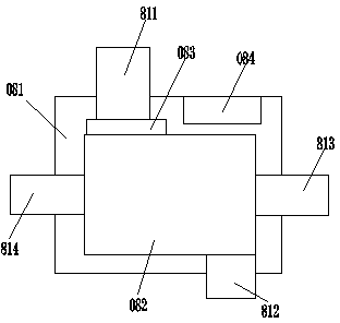
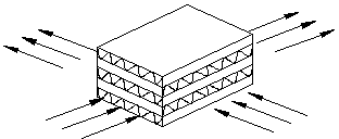
[0014] An airflow dryer capable of recovering waste heat from tail gas, comprising sequentially connected air heat exchanger 001, feed system 002, drying pipeline 003, cyclone separator 004, discharge screw conveyor 005 and tail gas pipeline 006, tail gas The air pipeline 006 passes through the fan 007, and the pipeline is connected to the waste heat recovery device 008. The waste heat recovery device 008 includes a casing 081 and a heat exchanger 082 arranged in the casing 081. The casing 081 is provided with an exhaust gas inlet and outlet (811 , 812) and air inlets and outlets (813, 814), the air outlets (814) are connected to the air heat exchanger 001 through pipes. The exhaust air inlet 811 is provided with an air filter 083 . A cleaning system 084 is additionally provided in the casing of the waste heat recovery device 008 . The heat exchanger 082 is a plate-fin heat exchanger.


PUM


Abstract

A pneumatic drier with a tail gas waste heat recycling function comprises an air heat exchanger, a feeding system, a drying pipeline, a cyclone separator, a discharging screw conveyer and a tail gas pipeline, wherein the tail gas pipeline is in pipe connection with a waste heat recycling device through a fan, the waste heat recycling device comprises a shell body and a heat exchanger arranged in the shell body, a tail gas inlet, a tail gas outlet, an air inlet and an air outlet are formed in the shell body, and the air outlet is in pipe connection with the air heat exchanger. According to the pneumatic drier with the tail gas waste heat recycling function, waste is reduced due to the recycling of waste heat, the waste heat recycling device is additionally arranged on the tail gas pipeline of the pneumatic drier so as to use the heat of tail gas to heat air entering the drier, dry air is then pre-heated, and therefore steam consumption is reduced, the purpose of saving energy and reducing emission is achieved, and good economic benefit and environmental benefit are obtained.

Description

technical field [0001] The invention belongs to the technical field of mechanical equipment, and relates to the manufacture of an airflow dryer, in particular to an airflow dryer capable of recovering tail gas waste heat. Background technique [0002] The airflow dryer is under the negative pressure state, using the high-speed hot air flow of about 160 ℃ ~ 180 ℃ after heat exchange through the heat exchanger, so that the dispersed powdery wet material is in a suspended state in the drying tube for transmission. Heat and mass transfer, and finally achieve the purpose of drying the powder; the powder enters the air lock from the cyclone separator and then enters the discharge screw conveyor to be discharged, and the hot and humid air is discharged to the atmosphere by the fan; the temperature of the hot and humid air is between 54 ° C and 65 ° C . The hot and humid steam discharged into the atmosphere contains a large amount of calorific value. Direct discharge to the atmosph...

Claims


Application Information

Patent Timeline
Patent Type & Authority Applications(China)
IPC IPC(8): F26B17/10F26B21/00F26B23/00
CPCY02P70/10
Inventor 刘亚明陈希明
Owner 江苏格兰特干燥浓缩设备有限公司
Why Eureka
Try Eureka