
Phase change energy storage device

A phase change energy storage and phase change unit technology, applied in energy storage, thermal storage equipment, lighting and heating equipment, etc. The effect of small charging volume, easy implementation and flexible structure

Active Publication Date: 2013-10-09
北京依米康散热技术有限公司
View PDF4 Cites 23 Cited by
  • Summary
  • Abstract
  • Description
  • Claims
  • Application Information

AI Technical Summary

Problems solved by technology

But this method often suffers from settling of metal particles or wires
At the same time, the paraffin structure is a continuous whole in this scheme, and it is easy to break the maintenance structure and cause the overall failure when undergoing phase transition expansion.

Method used


Image

  • Phase change energy storage device
  • Phase change energy storage device
  • Phase change energy storage device

Examples


Embodiment 1

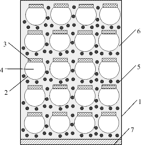
[0031] Embodiment 1 shows a typical application of the phase change energy storage device of the present invention, which absorbs and stores the heat generated during the operation of the laser through the paraffin phase change unit, so as to ensure that the laser will not be burned due to the intensive release of heat when working in a single pulse . figure 1 Schematic diagram of the phase change energy storage device.

[0032] Such as figure 1 As shown, the phase change energy storage device in this embodiment is composed of a shell 1 , a paraffin chamber 2 , a plastic cover 3 , paraffin 4 , metal particles 5 and a low melting point metal 6 . As the peripheral frame of the phase change energy storage device, the shell is closely attached to the heat source. The paraffin cavity 2, the plastic cover 3 and the paraffin 4 form a paraffin phase change unit, which is evenly filled in the shell. The paraffin phase change unit is the heat absorbing part of the phase change energy...


PUM

PropertyMeasurementUnit
Volumeaaaaaaaaaa
Melting pointaaaaaaaaaa
Diameteraaaaaaaaaa

Abstract

The invention relates to a phase change energy storage device which is characterized by being composed of an outer shell, a paraffin cavity, a plastic cap, paraffin, metal particles and low-melting-point metal. The outer shell is used as a peripheral frame of the phase change energy storage device to be tightly attached to a heat source. A paraffin phase change unit is composed of the paraffin cavity, the plastic cap and the paraffin and evenly filled into the outer shell. The paraffin phase change unit is a heat absorption portion of the phase change energy storage device. The metal particles are filled into the gap between the paraffin phase change unit and the outer shell. The low-melting-point metal is filled into the gap among the outer shell, the metal particles and the paraffin phase change unit so as to enable heat energy to be rapidly transmitted to the paraffin. The paraffin cavity is made of metal so as to be beneficial to heat transfer. The plastic cap is made of flexible plastics so as to compensate a volume expansion effect generated by the paraffin phase exchange. According to the phase change energy storage device, the high latent heat properties of the paraffin are utilized, and the energy storage performance is excellent. Meanwhile, the high heat conductivity properties of the metal particles and the low-melting-point metal are utilized, and the heat conductive performance is excellent. Finally, due to the design of a plurality of paraffin energy storage units, the normal operation of the system can be still ensured when a single energy storage unit in the system loses efficacy. The phase change energy storage device is simple in structure, easy to machine, small in low-melting-point metal charging amount, low in cost and capable of being widely used for heat energy utilization fields such as solar thermal power generation, hot water waste heat recovery, warm water bottles and warmers.

Description

technical field [0001] The invention relates to a phase change energy storage device, which uses a paraffin phase change unit to store heat, and uses metal particles and low melting point metals to form the heat transfer skeleton of the energy storage device, effectively improving the thermal conductivity of the energy storage device . The device of the present invention not only takes into account high latent heat and high thermal conductivity, but also has small filling amount of low melting point metal, low cost and simple structure, and can be widely used in the field of phase change energy storage. Background technique [0002] Phase change energy storage has gradually become an important means in the field of energy storage. Phase change materials mainly include inorganic phase change materials, organic phase change materials and composite phase change materials, each of which has its corresponding phase change melting point. In use, take solid-liquid phase change as ...

Claims


Application Information

Patent Timeline
IPC IPC(8): F28D20/02
CPCY02E60/14Y02E70/30
Inventor 郭瑞
Owner 北京依米康散热技术有限公司
Learn More