Long-distance large-range optical fiber strain generating device and generating method

An optical fiber strain and generating device technology, applied in the direction of using optical devices, measuring devices, instruments, etc., can solve the problems of short strain generation length, large strain value error, small strain range, etc. length, overcoming the effect of lower precision

Active Publication Date: 2013-10-09
CHINA ELECTRONIS TECH INSTR CO LTD
View PDF7 Cites 8 Cited by
  • Summary
  • Abstract
  • Description
  • Claims
  • Application Information

AI Technical Summary

Problems solved by technology

[0004] However, in actual use, due to the structural limitations of the constant-strength beam, it is difficult to strain the optical fiber with a length of more than 2m, and the strain range it produces is relatively small (about 0-2000με). Strain is generated, and the strained part of the optical fiber needs to be all pasted on the equal-strength beam, so the strain generated by the equal-strength beam cannot be fully transmitted to the optical fiber. The accuracy of strain generation is low and the error is large; while using the method of hanging heavy objects to generate strain, although it can generate strain on longer optical fibers, it is difficult to reach 20m, and the range of strain generation is also small, and the method of hanging heavy objects cannot To obtain the strain value directly, it needs to be converted according to the mass of the suspended weight and the elastic modulus parameter of the optical fiber, and the elastic modulus of the optical fiber is related to the material and doping of the optical fiber. The real elastic modulus is difficult to obtain and can only be obtained by theoretical Therefore, there is a large error between the calculated strain value and the actual strain value; the three-dimensional strain simulation platform has a complex structure, and the strain generation length is short, and the strain generation accuracy is also low

Method used


Image

  • Long-distance large-range optical fiber strain generating device and generating method

Examples


Embodiment 1

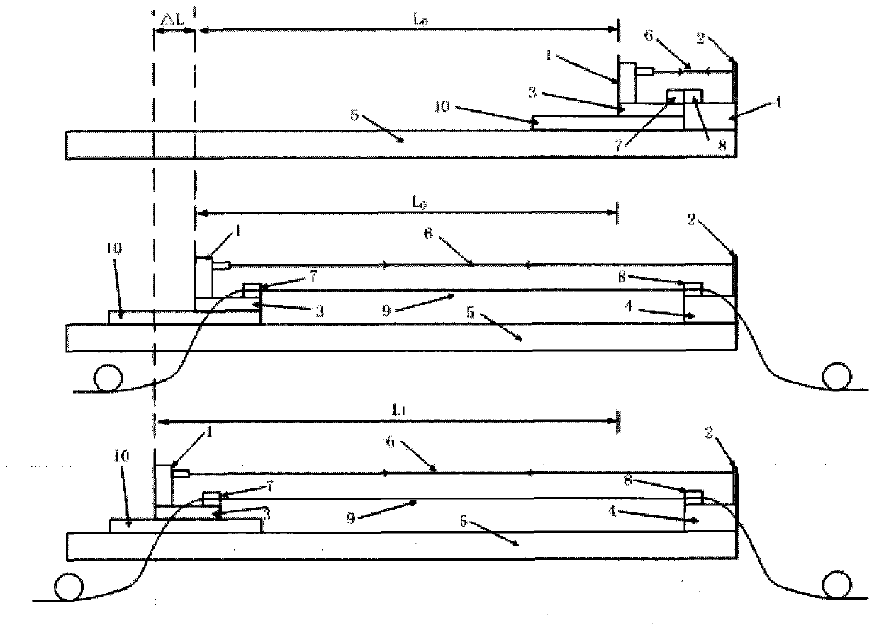
[0031] Such as figure 1 As shown, a long-distance and large-range optical fiber strain generation device of the present invention includes a dual-frequency laser interference length measurement device light source and a detector 1, a total reflection device 2, a left clamp carrying platform 3, and a right clamp carrying platform 4, which can move over a long distance Slide rail 5, distance measuring laser light path 6, left fixture 7, right fixture 8, tested optical fiber subject to strain 9, electric displacement stage base 10 fixed on the slide rail.

[0032] The invention uses a moving slide rail to convert distance measurement into displacement measurement, and accurately measures the original length and stretched length of the optical fiber through a high-precision dual-frequency laser length measurement device, thereby obtaining accurate strain measurement results. Dual-frequency laser measurement The displacement measurement accuracy of the long device is high and can b...

Embodiment 2

[0038] On the basis of the above examples, if figure 1 As shown, the present invention provides a long-distance and large-range optical fiber strain generation device, which includes a dual-frequency laser interference length measurement device, a light source and a detector 1 fixed on the left fixture carrying platform 3, and a total reflection device 2 fixed on the right fixture. On the platform 4, the light source and detector 1 of the dual-frequency laser interference length measurement device and the total reflection device 2 form a distance measuring laser optical path 6, which is used to measure the optical fiber displacement and optical fiber strain value. The present invention replaces the distance with displacement measurement measurement, greatly improving the accuracy of measurement.

[0039] Further, the left clamp 7 and the right clamp 8 are respectively set on the left clamp bearing platform 3 and the right clamp bearing platform 4, and the left clamp 7 and the ...

Embodiment 3

[0044] On the basis of the foregoing embodiments, further, as figure 1 As shown, the present invention also provides a long-distance and large-range optical fiber strain generation method, which includes the following steps:

[0045] Step A: forming a ranging laser light path;

[0046] Step B: record the displacement origin;

[0047] Step C: Move the base of the electronically controlled translation stage to the left, so that the strained part of the optical fiber under test is stretched straight, and then move the base of the electronically controlled translation stage to the right in small steps in the opposite direction. After each movement, the To start the BOTDR test the strain reading of the stretched section of the optical fiber, and record it as Y, when Y decreases to close to 0, record the reading of the dual-frequency laser interferometric length measurement device, and mark it as L0; the purpose of step C is to find out the The position of the stretched fiber segm...


PUM


Abstract

The invention provides a long-distance large-range optical fiber strain generating device. The device comprises a dual-frequency laser interference length measuring device light source, a detector and a full reflection device, wherein the dual-frequency laser interference length measuring device light source and the detector are fixed to a left clamp carrier platform, the full reflection device is fixed to a right clamp carrier platform, and the dual-frequency laser interference length measuring device light source, the detector and the full reflection device form a distance measuring laser light path which is used for measuring the optical fiber distance and the optical fiber strain value. By means of the scheme, a sliding rail is moved for a long distance so that distance measurement is changed into displacement measurement. The original length and the stretching length of an optical fiber strain generation portion can be precisely measured through the high-precision long-distance dual-frequency laser length measuring device. Strain is generated precisely through an electric control displacement platform. Strain generation precision is improved and the optical fiber length is increased, and the defects that an existing strain generating device is low in precision and short in optical fiber operation distance.

Description

technical field [0001] The invention belongs to the field of optical fiber strain generating devices, and in particular relates to a long-distance and large-range optical fiber strain generating device and a generating method. Background technique [0002] Optical fiber sensors are more and more used in engineering because they are not affected by electromagnetism, can work in harsh environments for a long time, are intrinsically safe, and have high sensitivity. Especially, optical fiber strain sensors are one of the main research directions of optical fiber sensors. It is widely used in construction, security, dams, industry and other fields. During the development, production and construction and acceptance of the optical fiber distributed strain tester (abbreviated as BOTDR), the strain generation device is required to generate a certain amount of strain for strain calibration of the optical fiber distributed strain tester. And carry out strain calibration on the optical...

Claims


Application Information

Patent Timeline
Patent Type & Authority Applications(China)
IPC IPC(8): G01B11/16
Inventor 闫继送袁明孙桂清王东升
Owner CHINA ELECTRONIS TECH INSTR CO LTD
Why Eureka
Try Eureka