Imaging method of super-speed coaxial framing coherent imaging light path

A technology of coherent imaging and imaging methods, applied in high-speed photography, optics, instruments, etc., can solve the problems of limited application, small spatial bandwidth range of images, and limited image information resolution of objects, and achieve high image resolution, The effect of short exposure times

Active Publication Date: 2013-10-09
INST OF FLUID PHYSICS CHINA ACAD OF ENG PHYSICS
View PDF6 Cites 15 Cited by
  • Summary
  • Abstract
  • Description
  • Claims
  • Application Information

AI Technical Summary

Problems solved by technology

At present, there is also digital holography that uses CCD as a multi-frame holographic recording medium, but the spatial bandwidth product of CCD is much smaller than that of holographic dry plate, so that each image has only a small spatial bandwidth range, which greatly limits the shape and scale of the object to be photographed. The resolution of image information such as , detail features, etc., the application is very limited
In addition, holographic framing technology is not suitable for ultrashort pulse laser (femtosecond laser) as light source, because the interference of object light and reference light cannot produce a sufficient number of holographic gratings (interference fringes), so that high-resolution large-scale viewing cannot be performed. Multiple imaging of the field
[0006] To sum up, the photoelectric framing technology can only achieve nanosecond time resolution, and the image converter framing technology can only achieve tens of picosecond time resolution at the fastest, and its spatial resolution is obviously insufficient; the spatial angle framing technology It is the easiest to implement but not coaxial imaging; holographic ultra-high-speed imaging technology has limited image bandwidth and limited number of shots, making it difficult to further improve time resolution

Method used


Image

  • Imaging method of super-speed coaxial framing coherent imaging light path
  • Imaging method of super-speed coaxial framing coherent imaging light path
  • Imaging method of super-speed coaxial framing coherent imaging light path

Examples


Embodiment Construction

[0024] The present invention will be further described below in conjunction with the accompanying drawings.

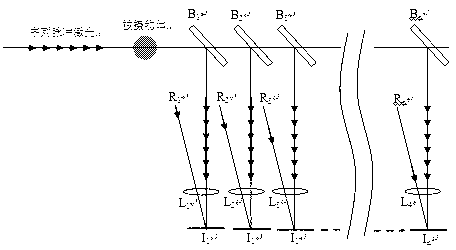
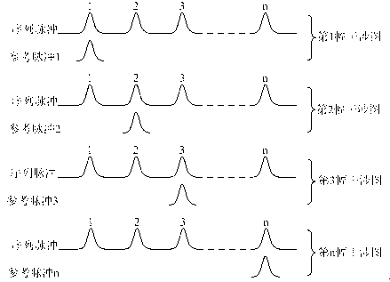
[0025] Such as figure 1 As shown, it is a schematic diagram of the principle of the present invention, the illuminating laser light transmitted or reflected from the subject is split by the beam splitter and transmitted to each coherence gate optical path together with the reference laser light. Each coherence gate optical path is composed of two arms, a series of pulsed laser beams are transmitted in one arm, and a reference pulsed laser beam is transmitted in the other arm, and the sequence pulses and reference pulses are transmitted to the image plane for convergence. Such as figure 2 As shown, when a sub-pulse of the sequence pulse overlaps with the reference pulse in time, an interference pattern will be formed on the image plane, which includes the phase, refractive index, density, Image information such as grayscale and transparency; the remaining sub-pulses ...


PUM


Abstract

The invention discloses an imaging method of a super-speed coaxial framing coherent imaging light path. According to the method, an object to be shot is lighted by coaxial train pulse laser light, a coherent shutter is achieved by means of the interference between a beam of reference light and the coaxial train pulse laser light so as to control the showing of image information, contained in a specific pulse of the train pulse laser light, of the object to be shot, image information contained in each pulse of the train pulse laser light can be shown respectively by means of multiple beams of reference light with different delays, and then framing imaging is achieved. According to the imaging method of the super-speed coaxial framing coherent imaging light path, mechanical or electronic shutter devices are not needed, super-speed and coaxial framing imaging of an transient physical process can be achieved by means of an all-optical light path, image resolution is high, imaging frequency is high, each image has a spatial bandwidth the same as that in the case of single imaging, the situation that the more the frames are, the smaller the bandwidth is does not exist, spatial discrimination sacrifice is avoided, and the imaging frequency is determined by train pulse separation.

Description

technical field [0001] The invention belongs to the technical field of high-speed imaging and laser interference, in particular to the field of ultra-high-speed coaxial framing coherent imaging. Background technique [0002] The current ultra-high-speed imaging technology can be divided into the following three types: [0003] The first type: framing camera technology, mainly including photoelectric framing camera and image transformation tube framing camera technology. Framing camera technology utilizes high-speed shutter framing (voltage strobe framing, electron beam scanning framing, and sampling scanning framing) to obtain sequential images. At present, the shortest exposure time of photoelectric framing cameras is about 5 ns, which makes it difficult to achieve ultra-high-speed imaging. The shortest exposure time of the zoom tube framing camera can reach about 35 ps, and the imaging frequency is about 6??10 8 ~5??10 9 fps, but when the image is regenerated through ...

Claims


Application Information

Patent Timeline
Patent Type & Authority Applications(China)
IPC IPC(8): G03B39/00
Inventor 陈光华李泽仁彭其先王德田邓向阳刘寿先阳庆国
Owner INST OF FLUID PHYSICS CHINA ACAD OF ENG PHYSICS
Why Eureka
Try Eureka