Fast oscillation starting crystal oscillator

A technology of crystal oscillator and main oscillation, which is applied in the direction of power oscillator, generator start-up, electrical components, etc., can solve the problems of start-up speed limit, etc., and achieve high start-up speed, fast speed, and large loop gain Effect

Inactive Publication Date: 2013-10-09
东南大学无锡分校
View PDF3 Cites 19 Cited by
  • Summary
  • Abstract
  • Description
  • Claims
  • Application Information

AI Technical Summary

Problems solved by technology

The traditional crystal oscillator uses a single NMOS tube as the amplifier tube, which can

Method used


Image

  • Fast oscillation starting crystal oscillator
  • Fast oscillation starting crystal oscillator
  • Fast oscillation starting crystal oscillator

Examples


Embodiment Construction

[0019] The present invention will be further described below in conjunction with the accompanying drawings.

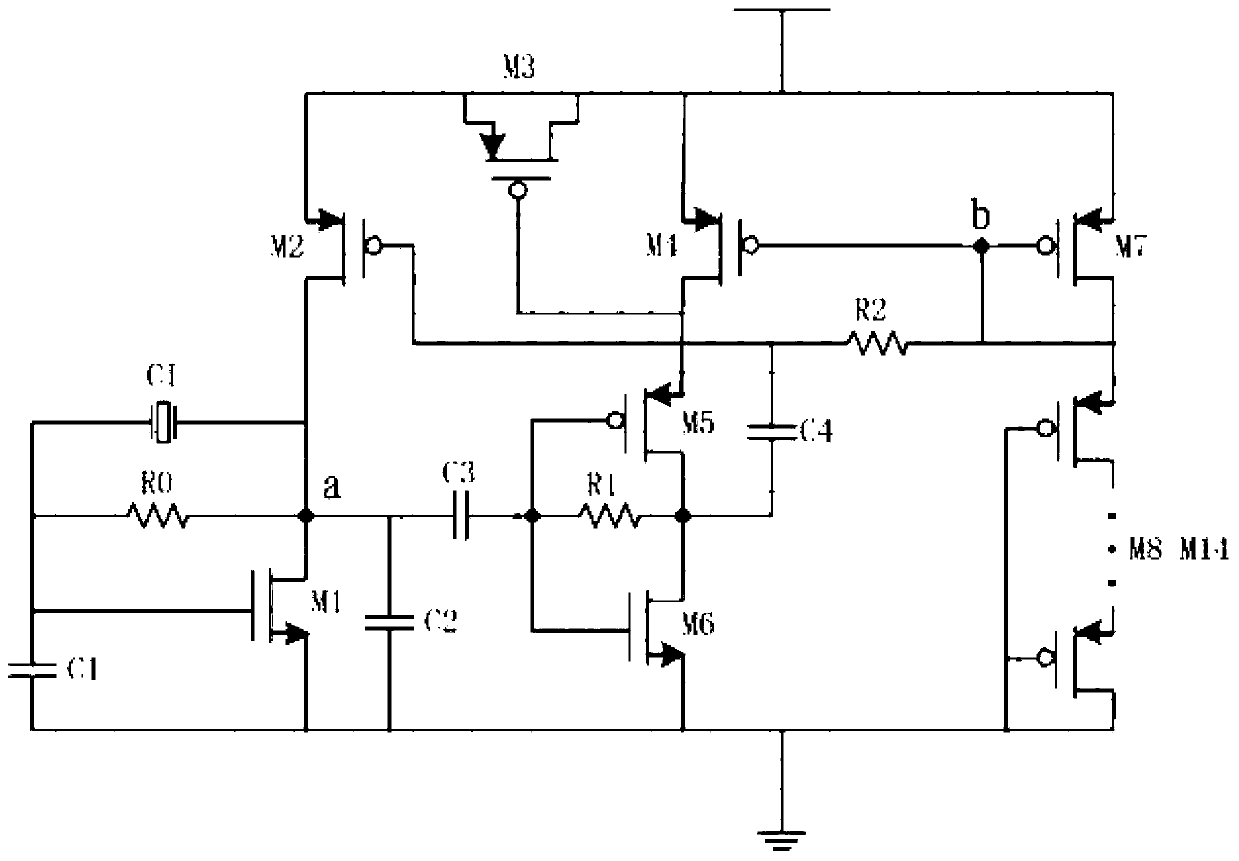
[0020] Such as figure 1 Shown is a fast start-up crystal oscillator, including main oscillation circuit, auxiliary oscillation branch and bias circuit. Each part is described in detail below.

[0021] The main oscillating circuit adopts a pierce structure, including a crystal oscillator CI, a zeroth resistor R0, a first capacitor C1, a first NMOS transistor M1, and a second capacitor C2; one end of the crystal oscillator CI, one end of the zeroth resistor R0, the first One end of the capacitor C1 is connected to the gate of the first NMOS transistor M1, the other end of the crystal oscillator CI, the other end of the zeroth resistor R0, the drain of the first NMOS transistor M1, and one end of the second capacitor C2 are connected to a contact , the other end of the first capacitor C1, the drain of the first NMOS transistor M1 and the other end of the second capacito...


PUM


Abstract

The invention discloses a fast oscillation starting crystal oscillator comprising a main oscillating circuit, an auxiliary oscillating branch and a biasing circuit. By means of partial gain of a buffer amplifier of the crystal oscillator, loop gain of oscillation frequency is complemented, the loop gain of the oscillation frequency is remarkably improved, and the speed of oscillation starting is increased. After the crystal oscillator is powered up and starts, a small signal component of the oscillation frequency in a voltage step is quickly amplified by a loop and finally begins to stabilize, and a stable signal is obtained. Due to the fact that the loop gain of the crystal oscillator is high, amplifying speed of a small frequency component is high, and therefore compared with a traditional crystal oscillator, the fast oscillation starting crystal oscillator has the advantages of being high in oscillation starting speed.

Description

technical field [0001] The invention relates to a fast start-up crystal oscillator. Background technique [0002] Since the first foreign quartz crystal oscillator came out in the early 1920s, the technology of quartz crystal oscillators has gradually matured. Because the Q value of the crystal resonator is very large, the crystal oscillator naturally has high frequency stability and excellent phase noise performance, so its application is very wide. As a high-precision and high-stability oscillator, crystal oscillators are widely used in various oscillating circuits such as color TVs, computers, and remote controls, as well as in communication systems for frequency generators, generating clock signals for data processing equipment, and for Certain systems provide a reference signal. [0003] When a portable handheld device or a wireless sensor network node transitions from sleep mode to working mode, its switching speed depends on the start-up time of the crystal oscillat...

Claims


Application Information

Patent Timeline
IPC IPC(8): H03L3/00
CPCH03B5/06H03B5/362H03B5/364
Inventor 吴建辉黄丹陈超黄成李红
Owner 东南大学无锡分校
Why Eureka
Try Eureka