
Manufacturing method of pinhole collimator

A technology of collimator and pinhole, applied in accelerators, electrical components, etc., can solve the problems of large heavy ion beam spot, low-energy scattering of heavy ion micro-beam, unsatisfactory pinhole shape, etc., to achieve good straightness and quality Good results

Active Publication Date: 2013-10-09
CHINA INSTITUTE OF ATOMIC ENERGY
View PDF7 Cites 6 Cited by
  • Summary
  • Abstract
  • Description
  • Claims
  • Application Information

AI Technical Summary

Problems solved by technology

[0005] In order to solve the problem that the pinhole shape of the existing pinhole collimator is not ideal, which makes the low-energy scattering of the heavy ion micro-beam serious, resulting in the heavy ion beam spot being too large and unable to meet the application requirements, etc., the present invention provides a The preparation method of pinhole collimator, the method steps are as follows:

Method used


Image

  • Manufacturing method of pinhole collimator
  • Manufacturing method of pinhole collimator

Examples


Embodiment

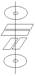
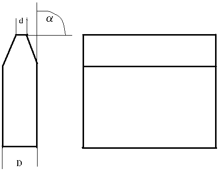
[0025] A preparation method of a pinhole collimator, the steps are as follows:

[0026] 1) Grinding of the blade

[0027] First, prepare the mold, which requires that the mold has two faces that are plane and perpendicularly intersect, and the intersection forms a straight edge; the blade is fixed on a plane of the mold, and the top of the blade edge is parallel to the straight edge and slightly protrudes above the the straight edge;

[0028] Fix the precision sandpaper on the flat plate, and then place the fixed blade and mold on the precision sandpaper, so that the blade is perpendicular to the precision sandpaper and the top of the blade edge is in contact with the precision sandpaper, and the relative movement of the mold and the precision sandpaper is controlled to make the blade edge The top is ground to be smooth and clean, and the thickness of the cutting edge is required to ensure that the collimated object will not be transmitted;

[0029] 2) Splicing of slit struc...


PUM

PropertyMeasurementUnit
Granularityaaaaaaaaaa

Abstract

The invention relates to a manufacturing method of a collimator. The problems that the shape of a pinhole of an existing pinhole collimator is not ideal, so that low-energy scattering of heavy ion microbeams is serious, heavy ion beam spots are large, and the application needs can not be met are solved. The manufacturing method of the pinhole collimator includes the following steps: 1) blade grinding, the top ends of cutting edges of blades are ground to be smooth and clean by using precision abrasive paper; 2) slit structure splicing, the cutting edges of the two blades are oppositely fixed on a bottom liner, and a slit is reserved between the cutting edges; 3) assembling, two slit structures are fixed together in an overlaying mode to form the pinhole of the pinhole collimator. The top ends of the cutting edges of the blades of the pinhole collimator manufactured according to the manufacturing method are good in straightness, the width of the spliced slit can be smaller than 1 micron, low-energy scattering ingredients of the heavy ion microbeams can be better lowered, the generated heavy ion beam spots are good in quality, and the application in heavy ion microbeam irradiation equipment is well achieved.

Description

technical field [0001] The invention relates to a preparation method of a collimator, in particular to a preparation method of a pinhole collimator. Background technique [0002] The heavy ion micro-beam irradiation device is an irradiation device that limits the heavy ion beam spot with a diameter of millimeter order produced by a conventional accelerator to the micron level by means of collimation or focusing. As a unique irradiation method, heavy ion microbeam irradiation has broad application prospects in the research of the single event effect mechanism of microelectronic devices, radiation biology, and materials science. Since the early 1980s, countries around the world have begun to use heavy ion microbeam irradiation to study single event effects, and have developed rapidly since the 1990s. So far, almost without exception, all countries with heavy ion accelerators have established heavy ion micro-beam irradiation devices and carried out research work on single even...

Claims


Application Information

Patent Timeline
IPC IPC(8): H05H7/00
Inventor 惠宁许谨诚郭刚沈东军
Owner CHINA INSTITUTE OF ATOMIC ENERGY
Learn More