Rotary electric machine driving system

一种旋转电机、驱动系统的技术,应用在控制系统、控制发电机、电动机控制等方向,能够解决再生转矩减小等问题,达到防止过多电流流过、抑制过多电流流过定子线圈、增加转矩的效果

Inactive Publication Date: 2013-10-09
TOYOTA JIDOSHA KK
View PDF9 Cites 7 Cited by
  • Summary
  • Abstract
  • Description
  • Claims
  • Application Information

AI Technical Summary

Problems solved by technology

Note that in the above description, when the rotary electric machine 10 is used as an electric motor in the range where the rotation speed is low, the motor torque decreases, however, when the rotary electric machine 10 is also used as a generator, for the same reason, in In the low rotation speed range, regenerative torque may be significantly reduced

Method used


Image

  • Rotary electric machine driving system
  • Rotary electric machine driving system
  • Rotary electric machine driving system

Examples


Embodiment Construction

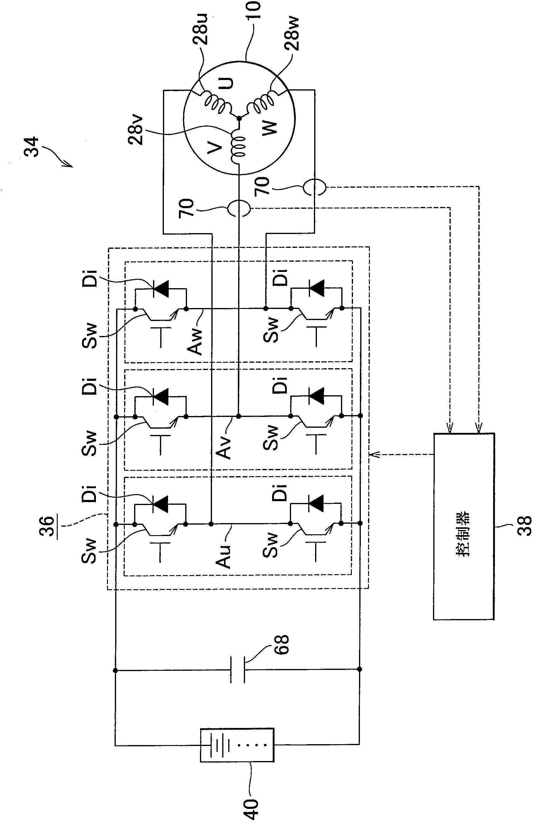
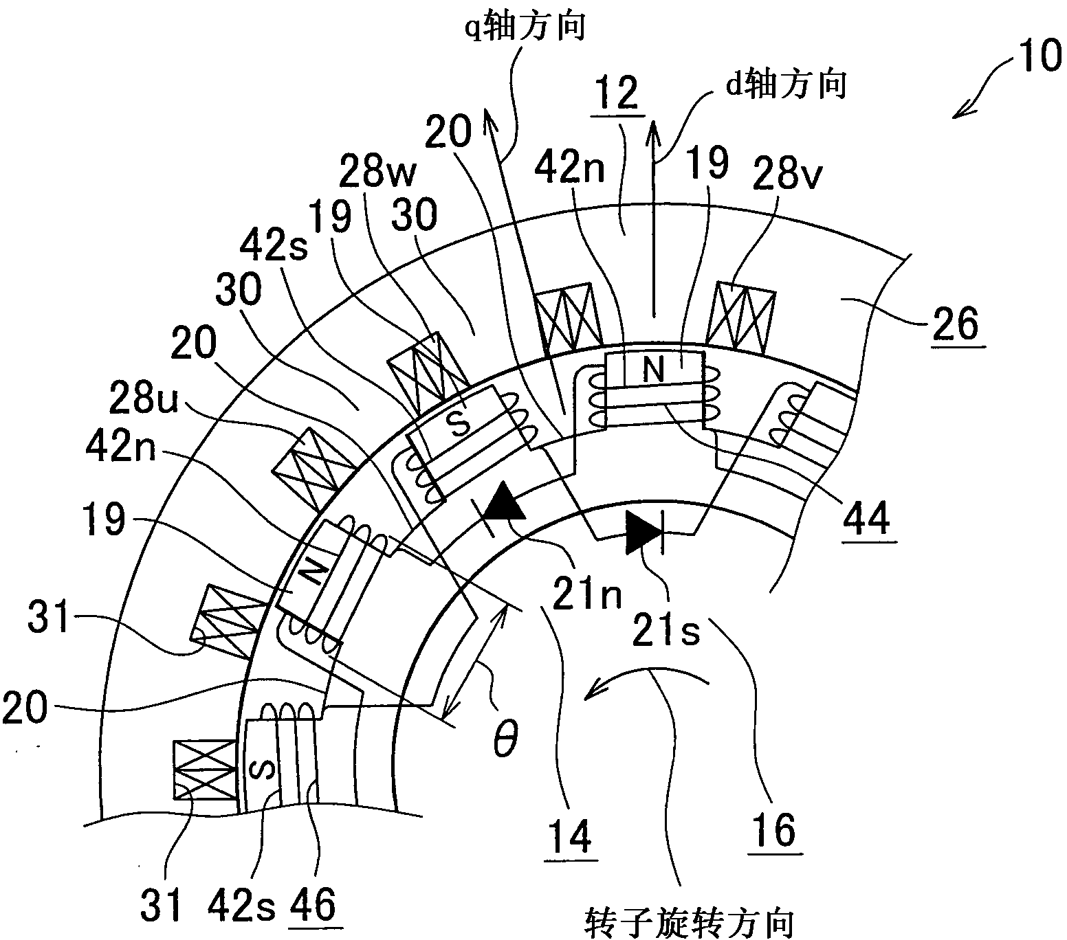
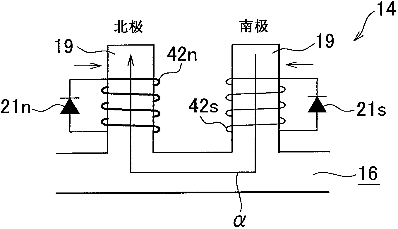
[0049] Figure 1 to Figure 8 and Figure 10 is a view showing an embodiment of the present invention. figure 1 is a view showing a schematic configuration of the rotating electric machine drive system according to the present embodiment. figure 2 is a schematic diagram partially showing a portion of the stator facing the rotor in this embodiment. Figure 3A is a schematic diagram showing a state in which magnetic flux passes through the rotor in this embodiment. Figure 3B is shown by calculating the magnitude of the flux linkage with the rotor coil while changing figure 2 A graph of the results obtained for the rotor coil width θ in the circumferential direction in the rotating electrical machine shown in . Figure 4 is a block diagram showing the configuration of the controller in the embodiment of the present invention. Such as figure 1 As shown, the rotating electric machine drive system 34 according to the present embodiment includes the electric rotating machin...


PUM


Abstract

A stator has multi-phase stator coils that are wound around a stator core by concentrated winding. A rotor has rotor coils that are wound at multiple portions of a rotor core in the circumferential direction and diodes that serve as rectifier unit that is connected to the rotor coils and that varies the magnetic characteristics of the respective rotor coils alternately in the circumferential direction. A rotary electric machine driving system includes a decreasing / increasing pulse superimposing unit that superimposes decreasing pulse current for a pulse-shaped decrease on a q-axis current command for passing currents through the stator coils and that superimposes increasing pulse current for a pulse-shaped increase on a d-axis current command.

Description

technical field [0001] The present invention relates to a rotary electric machine drive system including a rotary electric machine having a stator and a rotor arranged to face each other, a drive unit that drives the rotary electric machine, and a control unit that controls the drive unit. Background technique [0002] As described in Japanese Patent Application Laid-Open No. 2009-112091 (JP-A-2009-112091), there is known a rotating electrical machine in which a rotor is provided with a rotor coil and an induced current is generated in the rotor coil by a rotating magnetic field , so that the rotor generates torque. The rotating magnetic field is generated by the stator and includes space harmonics. Furthermore, with this rotor motor, an induced current is efficiently generated in the rotor coil, so that it can obtain an effect of effectively increasing the torque acting on the rotor. Figure 23 to Figure 25 A schematic configuration of a rotating electrical machine describ...

Claims


Application Information

Patent Timeline
Patent Type & Authority Applications(China)
IPC IPC(8): H02P21/00H02P25/02H02K19/12H02K19/36H02P21/12H02P21/22H02P25/08H02P27/04H02P29/02
CPCH02P25/026H02K19/12H02K21/042H02P21/0003H02K19/28H02P25/03
Inventor 山田英治水谷良治平本健二中井英雄蓑岛纪元
Owner TOYOTA JIDOSHA KK
Why Eureka
Try Eureka