Thyristor converter valve assembly

A technology of thyristor converter valve and thyristor control, which is applied in the direction of electrical components, electric solid-state devices, semiconductor devices, etc., can solve the problems of many water joints, high water leakage probability, and many branch water pipes, so as to simplify the design and prolong the service life Effect

Active Publication Date: 2013-10-16
XJ ELECTRIC
View PDF4 Cites 8 Cited by
  • Summary
  • Abstract
  • Description
  • Claims
  • Application Information

AI Technical Summary

Problems solved by technology

The large-frame type thyristor converter valve assembly assembles the thyristor-level control circuit and the water-cooled reactor, which mainly has the following disadvantages: First, the large-frame type thyristor converter valve assembly adopts the fixing method of frame aluminum profiles and supporting insulators, and its overall size is relatively small. Large, relatively difficult to assemble, transfer, test and transport; second, the large-frame thyristor valve assembly adopts a parallel small-diameter waterway design, which is difficult to design, with many waterway joints, high risk of water leakage, and easy blockage of the waterway; third, large All water joints of the frame-type thyristor converter valve assembly face downward and are located at the bottom. Water leakage from the upper valve assembly can easily cause short-circuit accidents in the electrical components of the lower valve assembly.
The small modular thyristor valve assembly does not contain a water-cooled reactor, which mainly has the following disadvantages: first, additional equipment is required to connect the valve assembly and the water-cooled reactor during the test, which is cumbersome; second, although the small modular thyristor valve assembly It is compact and small, but there are a lot of them, and the on-site valve tower installation workload is very large; third, there are many branch water pipes that need to be connected on site, and there are many water pipe joints connected on site, so the probability of water leakage is relatively high

Method used


Image

  • Thyristor converter valve assembly
  • Thyristor converter valve assembly
  • Thyristor converter valve assembly

Examples


Embodiment Construction

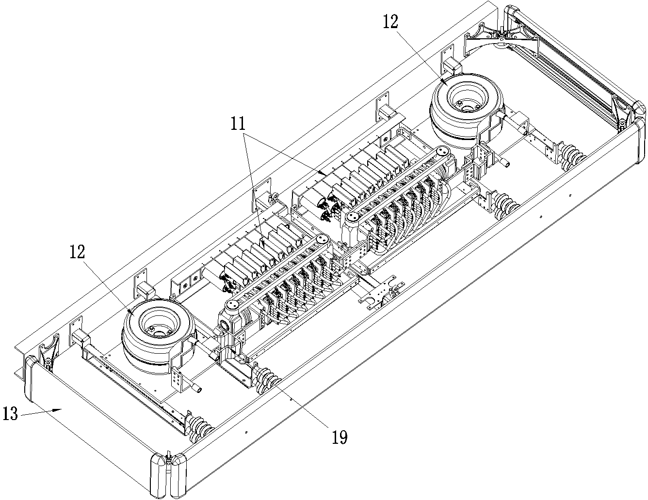
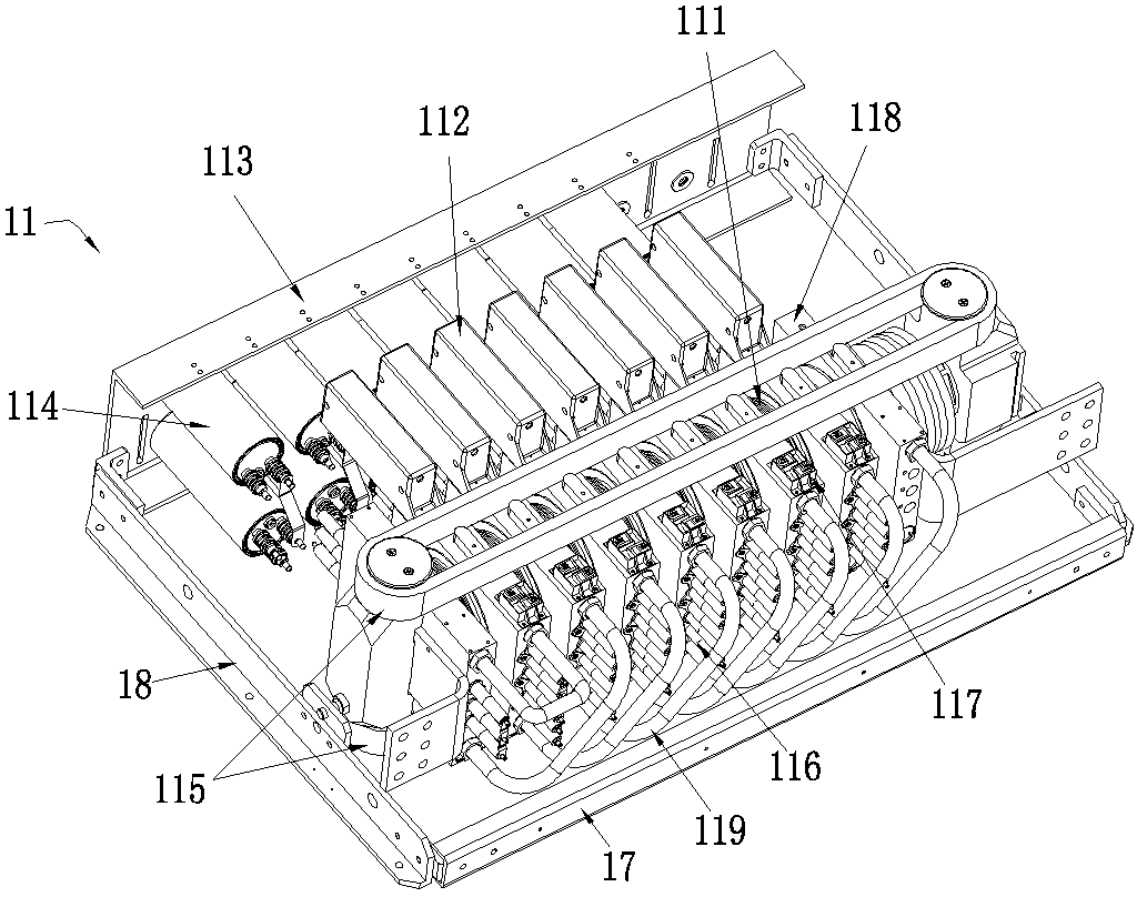
[0016] Examples of thyristor valve assemblies, such as Figure 1-3 As shown, the thyristor converter valve assembly includes a valve module 11 and a corresponding reactor 12. There are two valve modules 11 and two reactors 12 each, and they are both detachable and fixedly assembled on a frame-like base 13. Two reactors 12 are located at the left and right ends of the base 13 , and the valve module 11 is located between the two reactors 12 .

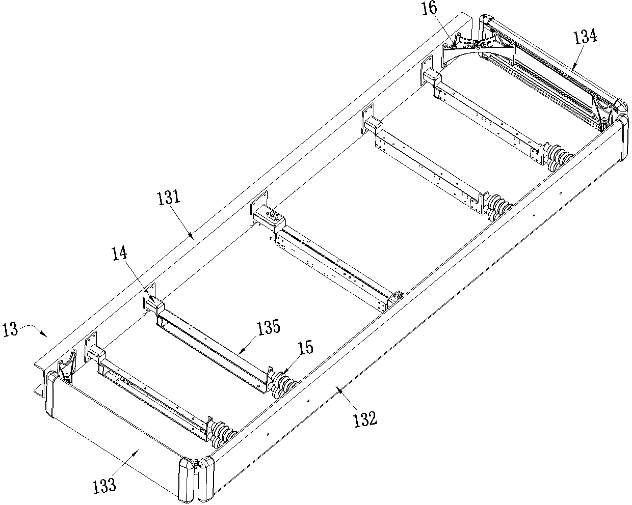
[0017] The base 13 is rectangular and includes a front frame 131, a rear frame 132, a left frame 133, a right frame 134 and a support beam 135 bridged between the front and rear frames. In this embodiment, the left frame 133, the right frame 134, the rear frame The frame 132 is made of aluminum profile, the front frame 131 and the support beam 135 are made of insulating material, the support beam 135 is bridged between the front and rear frames, and its front end is connected with the fixed connection block 14 provided on the front frame ...


PUM


Abstract

The invention relates to a high-power electrical electronic rectification and inversion apparatus, and specifically relates to a thyristor converter valve assembly applicable in high-voltage direct-current power transmission, direct-current ice melting equipment, SVC, etc. The thyristor converter valve assembly comprises valve modules and corresponding reactors. The valve module includes a frame. The valve modules and the reactors are fixedly mounted on a rectangular frame-type base in a detachable manner and distributed along the left-right direction of the base. The base includes a front border, a rear border, a left border, a right border and supporting beams bridging the front border and the rear border. The lengths of the left and right borders are smaller than that of the front and rear borders. The left and right borders are made of aluminium section material. One of the front and rear borders is made of aluminium section material, while the other one is made of insulation material. The thyristor converter valve assembly has the advantages of convenience for both transport and on-site assembly.

Description

technical field [0001] The invention relates to a high-power power electronic rectification and inverter device, in particular to a thyristor converter valve assembly used for high-voltage direct current transmission, direct current ice-melting equipment, SVC and the like. Background technique [0002] Thyristor converter valve components, as the core components of HVDC transmission systems, have been developed and applied for many years. [0003] At present, thyristor converter valve components mainly have two structural forms, one is a large frame type, and the other is a small module type. The large-frame type thyristor converter valve assembly assembles the thyristor-level control circuit and the water-cooled reactor, which mainly has the following disadvantages: First, the large-frame type thyristor converter valve assembly adopts the fixing method of frame aluminum profiles and supporting insulators, and its overall size is relatively small. Large, relatively difficul...

Claims


Application Information

Patent Timeline
Patent Type & Authority Applications(China)
IPC IPC(8): H01L25/07H01L23/473
Inventor 姚为正张建朱新华肖晋李申贾艳玲张承孙峻峰
Owner XJ ELECTRIC
Why Eureka
Try Eureka