
New s-band high-gain omnidirectional array antenna

An array antenna and high-gain technology, applied in the field of high-gain omnidirectional antenna arrays, can solve the problems of unable to solve the problem of omnidirectional transmission of wireless signals, low gain, limited communication distance, and inability to meet the communication system, etc. Addresses typically narrow bandwidth, high gain effects

Inactive Publication Date: 2016-09-14
NO 8357 RES INST OF THE THIRD ACADEMY OF CHINA AEROSPACE SCI & IND
View PDF3 Cites 0 Cited by
  • Summary
  • Abstract
  • Description
  • Claims
  • Application Information

AI Technical Summary

Problems solved by technology

[0003] Currently used vertically polarized omnidirectional antennas, one type uses dipoles, monopoles, or blade antennas, etc. Although this type of antenna has a simple structure and stable electrical performance, its low gain limits the improvement of communication distance; Another type of rod array antenna, etc., although it meets the gain requirements and can increase the communication distance, but due to the difficulty of processing and manufacturing, it cannot be formed at one time, and cannot meet the increasingly expanding needs of communication systems.
The gain of the patch antenna with directional radiation can meet the requirements, but the directivity of its pattern cannot solve the problem of omnidirectional transmission of wireless signals.

Method used


Image

  • New s-band high-gain omnidirectional array antenna
  • New s-band high-gain omnidirectional array antenna
  • New s-band high-gain omnidirectional array antenna

Examples


Embodiment 1

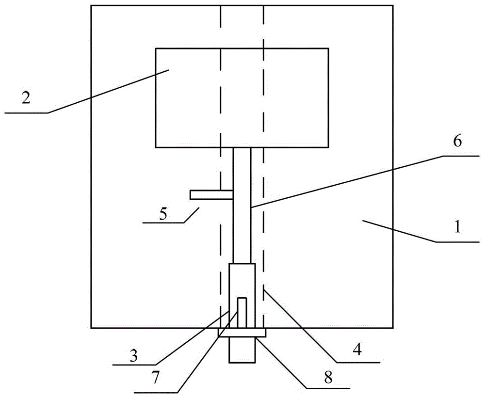
[0026] see figure 1 As shown, the new S-band high-gain omnidirectional array antenna of the present invention is composed of an antenna unit, and the antenna unit includes: a dielectric plate 1, a radiation patch 2, a feeder input terminal 3, a ground plate 4, and a feeder 6. In addition, Include matching stub 5;

[0027] The ground plate 4, the radiation patch 2, the feeder input end 3 and the matching stub 5 are distributed on the front and rear surfaces of the dielectric board 1;

[0028] The radiation patch 2 is connected to the feeder 6, the feeder 6 is connected to the line input end 3, the feeder input end 3 is connected to the inner core 7 of the coaxial connector, and the grounding plate 4 is connected to the sheath 8 of the coaxial connector; The shaft connector is a 50Ω SMA connector.

[0029] The antenna of the present invention uses a rectangular patch as the radiation patch 2, and adjusts the length and width of the radiation patch 2 to control the frequency ra...

Embodiment 2

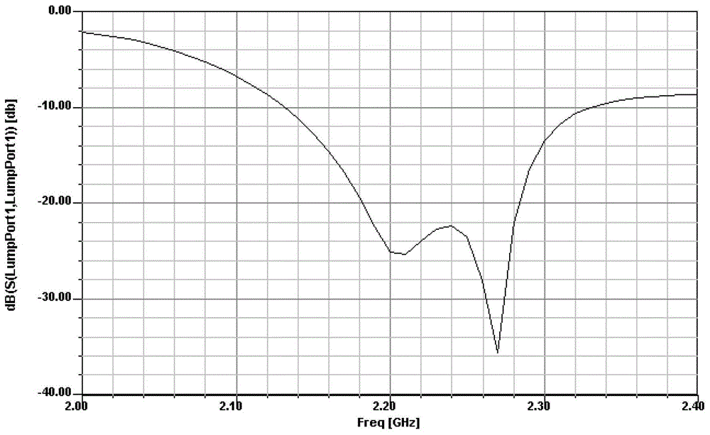
[0033] see figure 1 and 2 As shown, the S-band novel high-gain omnidirectional array antenna of the present invention is slightly different from Embodiment 1 in that the number of antenna elements is different. According to the requirements of the communication system, the number of elements of the array antenna can be adjusted, which can be 2, 3, or even 5-8 antenna units can be connected in series, and it is optimal to form an array of 4 antenna units connected in series.

[0034] When forming an array, after the radiation patches 2 of each antenna unit are connected in series through the feeder 6, the feeder 6 is then connected to the input end 3 of the feeder, and the matching stubs 5 of each antenna unit are distributed on the left and right sides of the feeder 6 at intervals, see figure 2 .

[0035] However, as the number of antenna units increases, the height of the antenna will increase sharply, and as the number of antenna units increases to a certain extent, the i...


PUM


Abstract

The invention discloses a novel S-wave-band high-gain omnidirectional array antenna. The antenna is formed by one or several antenna unit arrays. Each antenna unit comprises a medium plate (1), a radiation paster (2), a feed line input terminal (3), a grounding plate (4) and a feed line (6). In the arrays, the radiation pasters (2) of the antenna units are connected in series through the feed lines (6) and then the feed lines (6) are connected with the feed line input terminals (3). By using the antenna of the invention, a phenomenon of directional radiation of a current paster antenna direction pattern is changed and an omnidirectional radiation direction pattern is realized. The antenna units are used to form the arrays so that the antenna gain is large. A matching stub is introduced into the array antenna unit and a bandwidth of the array antenna is widened. And the bandwidth of the array antenna is greater than the typical bandwidth of the paster antenna. The antenna is applied in the wireless communication field and possesses characteristics that processing is easy; the gain is high; the bandwidth is wide; a profile is low; omnidirectional radiation is achieved.

Description

technical field [0001] The invention relates to a high-gain omnidirectional antenna array, especially a new type of high-gain omnidirectional array antenna in the S-band, more precisely, it is a universal, vertically polarized, omnidirectional Radiating high-gain antenna array. Background technique [0002] In a wireless communication system, due to the uncertainty of the location of the receiving antenna, in order to ensure the smooth communication link, an omnidirectional antenna is generally used at the signal transmitting end to transmit wireless signals. At present, high-gain omnidirectional array antenna technology is one of the effective means to further improve wireless communication capabilities, so the application of high-gain omnidirectional array antennas in wireless communication systems has also become a research hotspot. [0003] Currently used vertically polarized omnidirectional antennas, one type uses dipoles, monopoles, or blade antennas, etc. Although th...

Claims


Application Information

Patent Timeline
Patent Type & Authority Patents(China)
IPC IPC(8): H01Q21/30
Inventor 董加伟章飚李永翔
Owner NO 8357 RES INST OF THE THIRD ACADEMY OF CHINA AEROSPACE SCI & IND
Learn More