High-rigidity large-torque vertical machining center

A vertical machining center and high torque technology, applied in metal processing, metal processing equipment, metal processing machinery parts, etc., can solve the problems of low production efficiency, high maintenance cost and high tool change failure frequency of ferrous metal processing, and achieve Improvement of machine tool structure, improvement of production efficiency, and reduction of tool change failures

Inactive Publication Date: 2013-10-23
HANGZHOU DATIAN CNC MACHINE TOOL
View PDF10 Cites 8 Cited by
  • Summary
  • Abstract
  • Description
  • Claims
  • Application Information

AI Technical Summary

Problems solved by technology

[0009] The invention provides a high-rigidity and high-torque vertical machining center, which provides high-efficiency and low-energy-consumption CNC machine tools for ferrous metal processing, and mainly solves the energy waste caused by the use of high-power main motors in the prior art; the use of high and low gear boxes is expensive, High cost of use and maintenance; insufficient rigidity for heavy-duty cutting machine tools, high frequency of tool change failures; low production efficiency and high energy consumption for ferrous metal processing

Method used


Image

  • High-rigidity large-torque vertical machining center
  • High-rigidity large-torque vertical machining center
  • High-rigidity large-torque vertical machining center

Examples


Embodiment 1

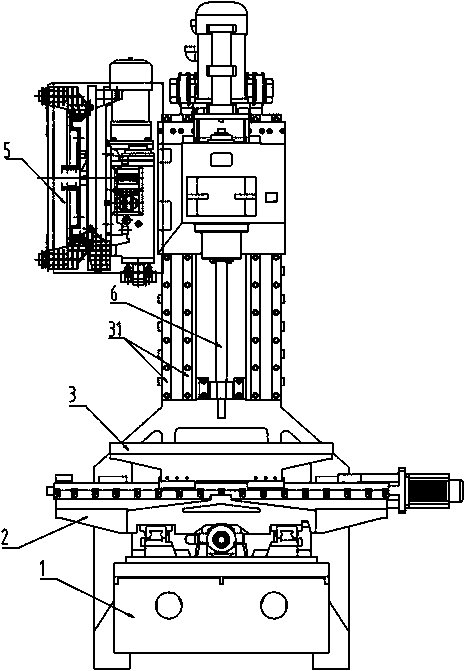
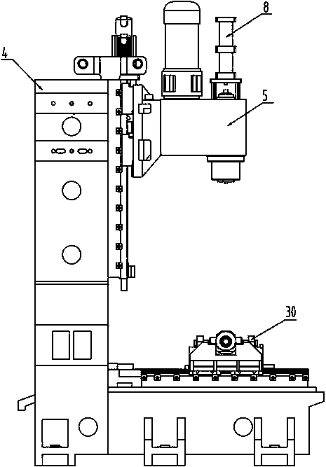
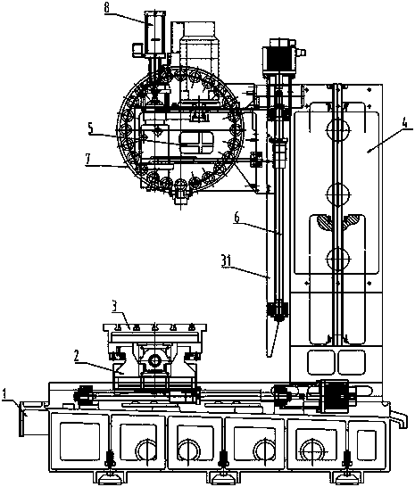
[0048] Embodiment 1: The high-rigidity and high-torque vertical machining center of this example, such as figure 1 , figure 2 , image 3 , including a honeycomb bed 1, which is provided with a double-layer densely ribbed saddle 2, a workbench 3, and a herringbone frame column 4 on the bed, which is slidably connected to a headstock 5 through a guide rail. , the workbench 3 is provided with a workbench guide rail 30, and the guide rail of the herringbone frame column 4 is a linear ball guide 31 larger than the workbench guide rail specification. The herringbone frame column is provided with a ball screw 6, the spindle box is threadedly connected to the ball screw, the spindle box is provided with a tool magazine 7 and a tool cylinder 8, and the spindle 9 of the spindle box is provided with a spindle positioning device, such as Figure 4 , the spindle positioning device includes a positioning pin provided on the spindle 9, a detection switch 29 is fixed on the spindle box by ...

Embodiment 2

[0050] Embodiment 2: the high-rigidity and high-torque vertical machining center of this example, such as Figure 5 , Figure 6 , including a honeycomb bed 1, which is provided with a double-layer densely ribbed saddle 2, a workbench 3, and a herringbone frame column 4 on the bed, which is slidably connected to a headstock 5 through a guide rail. , the workbench 3 is provided with a workbench guide rail 30, and the guide rail of the herringbone frame column is a guide rail 32 larger than the workbench guide rail width. The herringbone frame column is provided with a ball screw 6, the spindle box is threadedly connected to the ball screw, the spindle box is provided with a tool magazine 7 and a tool cylinder 8, and the spindle 9 of the spindle box is provided with a spindle positioning device, such as Figure 7 , the spindle positioning device includes a positioning pin provided on the spindle 9, a detection switch 29 is fixed on the spindle box by a detection switch bracket 2...

Embodiment 3

[0052] Embodiment 3: the high-rigidity and high-torque vertical machining center of this example, such as Figure 8 , the spindle positioning device includes a mounting seat 22 and a base plate 23 fixed on the spindle box, the base plate is provided with an encoding shaft 24, the encoding shaft is connected with an encoder synchronous pulley 25, and the encoder synchronous pulley is connected to the main shaft 9 through a synchronous belt. , the encoder synchronous pulley is connected to the encoder 27 through the encoder mount 26 . The vertical machining center is equipped with electrical and numerical control systems. The spindle box is provided with a main motor 10, the main motor is connected to the first synchronous pulley 13 through the main motor pulley 11 and the synchronous belt 12, and the first synchronous pulley is connected to the main shaft through the first shaft body 14 and the first gear 16. The gear is threaded on the third shaft body 33 . A main shaft spee...


PUM


Abstract

The invention relates to a vertical machining center, in particular to a high-rigidity large-torque vertical machining center. The machining center mainly solves the technical problems that high-grade and low-grade reduction boxes are high in price, high speed gears operate in ultimate states, the failure rate is high, the use and maintenance costs are high, the machining requirements of other reduction ratios such as 1:2/1:3 cannot be met, the rigidity of a spindle is poor, and the tool changing failure frequency is high in vertical machining in the prior art. The machining center comprises a honeycomb type bed, wherein a double-layer ribbed carriage and a workbench are arranged on the honeycomb type bed; a herringbone frame upright is also arranged on the bed and connected with a spindle box by a guide rail in a sliding manner; a ball screw is arranged on the herringbone frame upright; the spindle box is in threaded connection with the ball screw; a tool magazine and an unclamping cylinder is arranged on the spindle box; the spindle box is internally provided with a 1:2/1:4/1:8 speed reducer; a spindle location device is arranged on a spindle of the spindle box; and the vertical machining center is provided with an electric and numerical control system.

Description

technical field [0001] The invention relates to a vertical machining center, in particular to a high-rigidity and high-torque vertical machining center. Background technique [0002] The existing machining center has poor rigidity of the machine tool spindle device; when the spindle speed is lower than the rated speed, the power of the main motor decreases proportionally with the speed drop, resulting in poor cutting efficiency and energy waste. [0003] Existing machining centers are mainly used in the processing of non-ferrous metal parts, ferrous metal parts, and new difficult-to-machine material parts. In order to improve the machining accuracy and cutting efficiency of parts, the existing technology is developing in the direction of high speed and high precision. The spindle speed is generally 8000- 15000rpm, the electric spindle can reach more than 80000rpm; but the cutting torque and effective power are small at low speed, which cannot meet the requirements of rough m...

Claims


Application Information

Patent Timeline
Patent Type & Authority Applications(China)
IPC IPC(8): B23Q37/00B23Q1/01B23Q5/18B23B19/02
Inventor 王元庆
Owner HANGZHOU DATIAN CNC MACHINE TOOL
Why Eureka
Try Eureka