Assembling jet device

An ejector and assembled technology, applied in the field of ejectors, can solve the problems of increasing the structural complexity of the ejector, increasing the difficulty of processing, and non-adjustable nozzles. Effect

Inactive Publication Date: 2013-10-23
XI AN JIAOTONG UNIV
View PDF11 Cites 1 Cited by
  • Summary
  • Abstract
  • Description
  • Claims
  • Application Information

AI Technical Summary

Problems solved by technology

[0003] The utility model patent "A Jet" (public number: CN201596476U) discloses a jet, which consists of a feeding pipe, a suction pipe, a flange, and a nozzle, and a check valve is provided at the outlet of the nozzle ; Its advantage is that it effectively prevents the backflow phenomenon that occurs when the water flow is not fast enough or the water pressure is unstable, but a one-way valve is provided at the outlet of the nozzle, which increases the complexity of the structure of the jet and increases the cost
[0004] The invention patent "Ejector Device" (publication number: CN1112179) discloses a vacuum generating device that can reduce the pressure required for sewage transmission in a vacuum drainage system. It includes a liquid-driven ejector, and the discharge pipe hole of the ejector is basically columnar. , but this overall structure increases the difficulty of processing, and the position of the nozzle is fixed and not adjustable

Method used


Image

  • Assembling jet device

Examples


Embodiment Construction

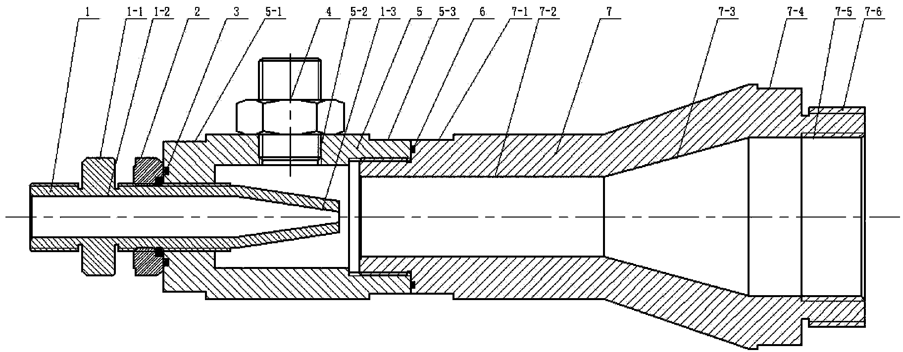
[0012] See figure 1 , The present invention includes a nozzle 1, a suction cavity 5 and a spray cavity 7. The nozzle 1 is composed of a nozzle bayonet 1-1 of an external hexagon wrench, a nozzle throat 1-2 with external threads, and a cone-shaped nozzle 1-3. The cavity 5 is composed of the inlet of the inner suction cavity, the outlet wrench bayonet 5-1, 5-3 and the internal threaded interface 5-2 between the two suction cavity wrench bayonet. The spray cavity 7 is composed of an external thread Jet cavity wrench bayonet 7-1, annular cavity 7-2, flared jet nozzle 7-3, jet cavity outlet wrench bayonet 7-4, internal thread interface 7-5 and external thread interface 7-6, nozzle 1. The throat pipe 1-2 and the suction cavity inlet wrench bayonet 5-1 are threadedly connected, and an "O" sealing ring 3 for radial sealing is arranged between the two, and is locked by a nylon lock nut 2. Dead, the nylon lock nut 2 is axially sealed to prevent oil leakage and is used to adjust the posi...


PUM


Abstract

The invention relates to an assembling jet device, which comprises a nozzle, a suction chamber, and a jet chamber, wherein the nozzle is composed of an outer hexagon wrench bayonet, a venturi, and a tapered nozzle; the suction chamber is composed of a left face spanner bayonet, a right face spanner bayonet, and three internal thread interfaces; the jet chamber is composed of a left face spanner bayonet, a right face spanner bayonet, a ring-shaped chamber body, a horn-shaped jet orifice, an internal thread interface, and an external thread interface; an external thread is formed in the external surface of the venturi in the nozzle, is connected with an internal thread in the left part of the suction chamber, and is dead locked through nylon lock nuts; an internal thread of the right part of the intake cavity is connected with the external thread of the left of the ring-shaped cavity body of the jet cavity; the internal thread or the external thread in the right of the jet chamber is connected with an oil pipe. According to the jet device, the nozzle can be replaced; the position of the nozzle in the suction chamber can be adjusted through the nylon lock nuts; therefore, requirements of simple process, convenience in assembling, flexible arrangement, reliable working, low noise, and zero pollution are satisfied.

Description

Technical field [0001] The invention relates to a jet, in particular to an assemblable jet used for lubricating and returning oil to ultra-precision electric spindles or other dynamic and static pressure functional components. Background technique [0002] The jet has the advantages of simple installation, flexible layout, constant long-term operation performance, reliable work, low noise, no pollution, long service life, etc. It only needs to be equipped with a certain working medium and pressure to complete the suction of gas or liquid. [0003] The utility model patent "A Jet" (Publication Number: CN201596476U) discloses a jet, which is composed of a feeding tube, a suction tube, a flange, and a nozzle, and a check valve is provided at the outlet of the nozzle ; Its advantage is that it effectively prevents the backflow phenomenon that occurs when the water flow is not fast enough or the water pressure is unstable, but the one-way valve at the outlet of the injection port increa...

Claims


Application Information

Patent Timeline
Patent Type & Authority Applications(China)
IPC IPC(8): F16N21/00F16N31/00
Inventor 陈耀龙查俊陈晓燕刘可佳
Owner XI AN JIAOTONG UNIV
Why Eureka
Try Eureka