Optical measuring instrument temperature control method and device, and optical measuring instrument

A technology of temperature control equipment and optical measurement, applied in optical radiation measurement, scientific instruments, photometry, etc., to achieve high precision, comprehensive temperature control, and good stability

Active Publication Date: 2013-10-23
RAINTREE SCI INSTR SHANGHAI
View PDF10 Cites 5 Cited by
  • Summary
  • Abstract
  • Description
  • Claims
  • Application Information

AI Technical Summary

Problems solved by technology

Then the remaining heat will transfer heat to the environment in the system and other components through various heat transfer methods.

Method used


Image

  • Optical measuring instrument temperature control method and device, and optical measuring instrument
  • Optical measuring instrument temperature control method and device, and optical measuring instrument
  • Optical measuring instrument temperature control method and device, and optical measuring instrument

Examples


specific Embodiment approach 1

[0061] In this embodiment, the first, second and fourth temperature control elements are realized by thermal insulation components, specifically:

[0062] 1. Control of heat source and incident, outgoing and lens group modules

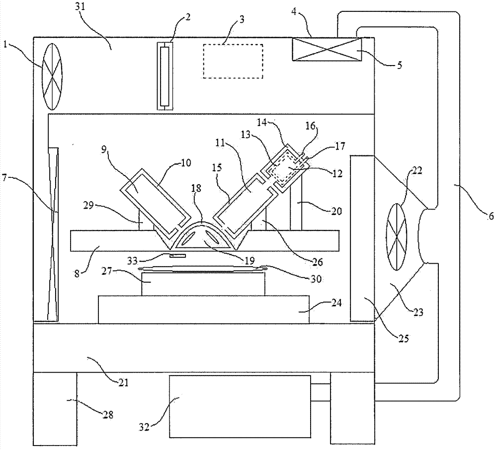
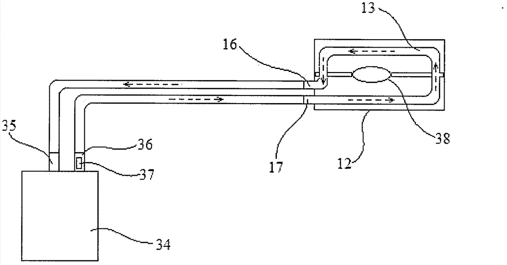
[0063] refer to figure 2 , in this system, the light source 38 buried in the light source module 12 is the largest heat source, in order to take away the heat generated by it, water pipes 13 are placed around it. The cold water flows out from the water outlet 36 of the chiller to the water inlet 17 of the light source module, and then flows through the pipe 13 to take away the heat from the light source to become hot water, and finally flows back to the water inlet 35 of the chiller through the water outlet 16 . The hot water is refrigerated by the chiller and then flows out from the water outlet by the pump, continuously circulating, thus taking away the heat. There are pumps, exhaust fans, water tanks, etc. inside the chiller, and the chiller is a...

specific Embodiment approach 2

[0072] The system structure of Scheme 2 is the same as Scheme 1, and the ambient temperature control of the optical path space in the measurement area is also the same as Scheme 1. The difference is that in Scheme 1, the first, second and fourth temperature control elements are all wrapped with heat insulating materials to avoid being affected by heat; in this scheme, these temperature control elements are uniformly cooled by a water cooling device. module.

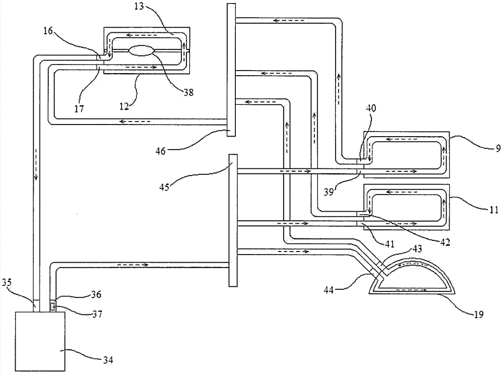
[0073] In a preferred embodiment, the first, second and fourth temperature control elements and the third temperature control element share a set of water-cooling pipelines. For the wiring diagram of the water-cooling pipelines, please refer to image 3 . Water pipes are laid inside the light source module 12, the incident module 11, the exit module 9 and the lens group module 19 for feeding cold water. Water pipes should try to wrap each module as much as possible. In the series-parallel design of pipelines, it is con...


PUM


Abstract

The conventional temperature control device for an optical measuring instrument only cools down a light source module, and cannot maintain a stable temperature of other modules and optical path space in the optical measuring instrument, so that a measuring result is not accurate. The invention provides an optical measuring instrument temperature control method and device, and an optical measuring instrument. The device comprises a first temperature control element (15) which is thermally coupled with an incident module (11) of the optical measuring instrument, and a second temperature control element (10) which is thermally coupled with an emitting module (9) of the optical measuring instrument. The first temperature control element and the second temperature control element control the temperature of the modules to prevent the modules from being influenced by light source heat. Preferably, the device also comprises an air supply device (4,2,1,7,33,3) which is used for providing airflow on an air path to keep the temperature within a certain range. The air path covers the optical path space between a wafer and a measuring mechanism of the optical measuring instrument, so that the stable temperature in the optical path space is maintained.

Description

technical field [0001] The present invention relates to temperature control for the field of optical measurement, especially temperature control for optical thin film measurement. Background technique [0002] With the rapid development of semiconductor miniaturization process technology, the structure size has been pushed from micron to deep submicron, and then entered the nanometer era. It is reported that the 28nm new process of cooperation between TSMC and ARM will be mass-produced by the end of 2011. In order to meet the needs of the miniaturization process, its key technologies such as photolithography technology and thin film technology have encountered huge challenges. The advanced measurement technology is the guarantee of better process control and higher yield. [0003] Thin film measurement is one of the most important means to test product quality in the semiconductor industry, and its measurement accuracy and long-term stability are the most important criteri...

Claims


Application Information

Patent Timeline
Patent Type & Authority Applications(China)
IPC IPC(8): G01J1/02
Inventor 王英毕昕周善淮
Owner RAINTREE SCI INSTR SHANGHAI
Why Eureka
Try Eureka