Circular polarization light panel and making method thereof

A technology of circularly polarized light and polarizing layer, applied in the field of circularly polarized light plate and its manufacturing, can solve the problems of thick total thickness of circularly polarized light plate, unsuitable for circularly polarized light plate, etc., and achieve the effect of excellent anti-reflection performance

Active Publication Date: 2013-10-23
SUMITOMO CHEM CO LTD
View PDF12 Cites 12 Cited by
  • Summary
  • Abstract
  • Description
  • Claims
  • Application Information

AI Technical Summary

Problems solved by technology
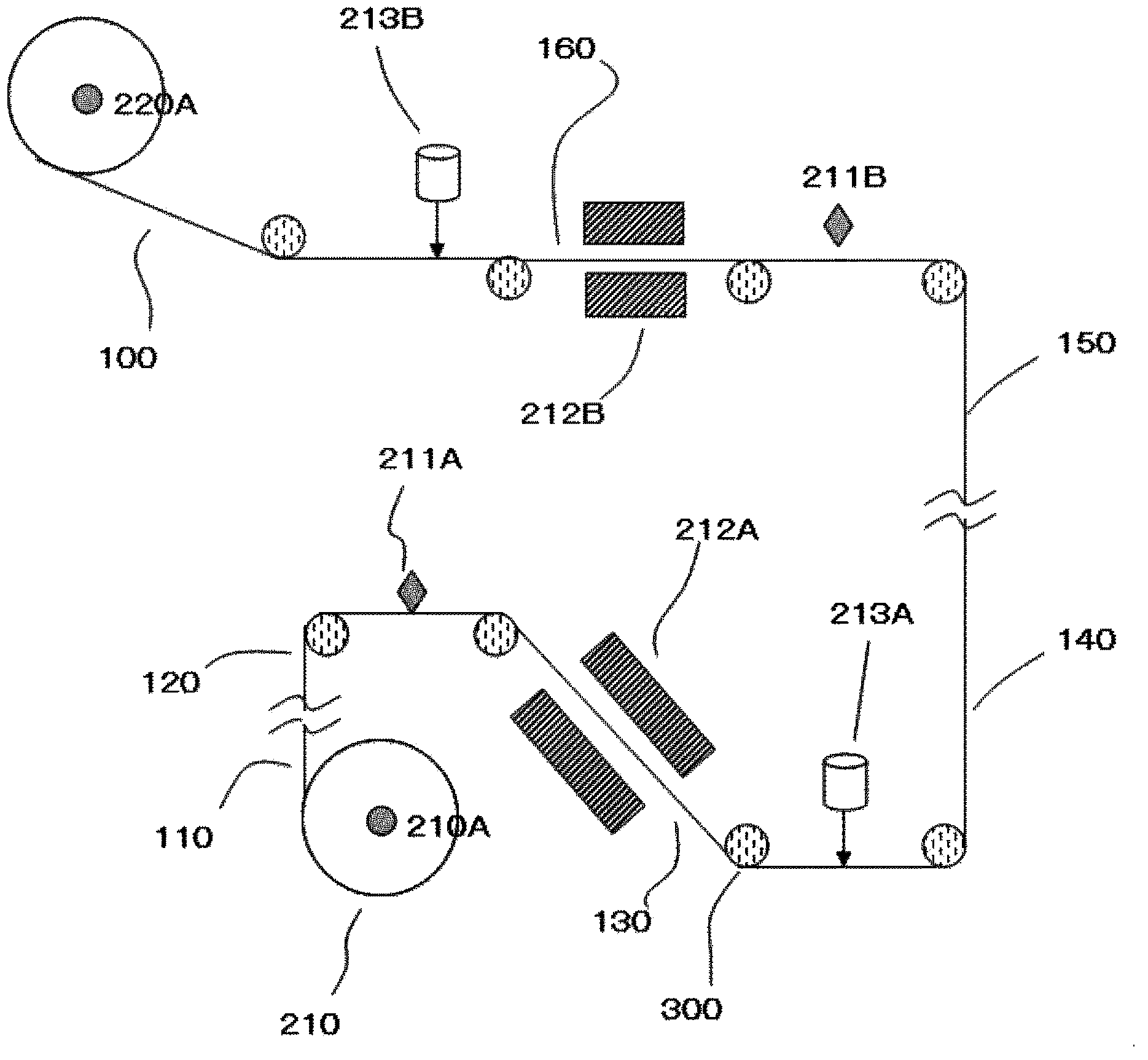
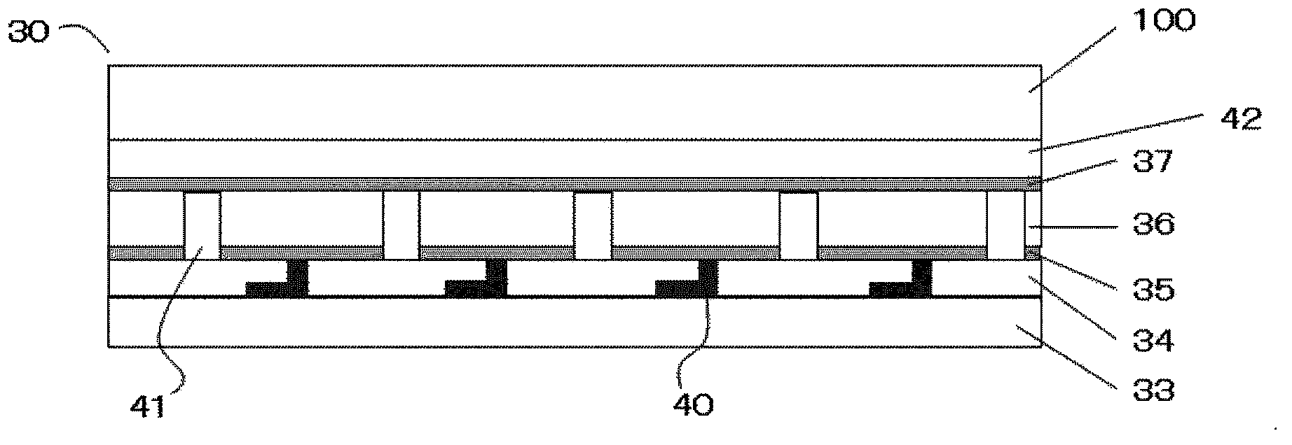
However, it cannot be avoided that the total thickness of such a circularly polarizing plate is very thick, and it is not suitable as a circularly polarizing plate for use in display devices that are currently required to be thinner.

Method used


Image

  • Circular polarization light panel and making method thereof
  • Circular polarization light panel and making method thereof
  • Circular polarization light panel and making method thereof

Examples


Embodiment 1

[0284] (Preparation of composition (1) for liquid crystal retardation layer formation)

[0285] The following components were mixed, and it stirred at 80 degreeC for 1 hour, and obtained the composition (1) for liquid crystal retardation layer formation.

[0286] Polymeric liquid crystal compound; trade name LC-242 manufactured by BASF Co., Ltd. 100 parts

[0287]

[0288] polymerization initiator;

[0289] 2-Methyl-1-[4-(methylthio)phenyl]-2-morpholinylpropan-1-one

[0290] (Irgacure (Irgacure) 907: Manufactured by Ciba Specialty Chemicals Co., Ltd.) 3 parts

[0291] Solvent; 250 parts of cyclopentanone

[0292] (Preparation of composition (1) for photo-alignment layer formation)

[0293] The following components were mixed, and it stirred at 80 degreeC for 1 hour, and obtained the composition (1) for photo-alignment layer formation.

[0294] Photo-alignment material; 5 parts

[0295]

[0296] Solvent; 95 parts of cyclopentanone

[0297] (Preparation of Polarizin...

Embodiment 2

[0335] Same as in Example 1, a photo-alignment layer was formed on one surface of the retardation film (the polarization direction of polarized light UV was 60° relative to the slow axis of the retardation film), and a liquid crystal retardation layer was formed on the photo-alignment layer. Then, on the surface of the retardation film with liquid crystal retardation that is opposite to the surface of the liquid crystal retardation, form a photo-alignment layer (the polarization direction of the polarized light UV is 15° relative to the slow axis of the retardation film), where the photo-alignment A polarizing layer is further formed on the layer to make the circular polarizing plate (2).

[0336] The total thickness of the circular polarizing plate (2) was measured by a contact film thickness meter, and it was 46 μm.

[0337] Same as in Example 1, the circular polarizing plate (2) is bonded to the reflector using an adhesive, and the reflectance is measured. The light in the ...

reference example 1

[0342] An iodine-PVA polarizing plate (manufactured by Sumikaran Sumitomo Chemical Co., Ltd. with a thickness of 105 μm) as a polarizing plate was cut into small pieces of 100×100 mm, and the absorption axis was set at 0°. The 1 / 2 wavelength plate used in Example 1 was cut into 100 mm. For small pieces of ×100 mm, the slow axis was set at 15°, and the 1 / 4 wavelength plate used in Comparative Example 1 was cut into small pieces of 100×100 mm, and the slow axis was set at 75°. The sheets were laminated using an acrylic adhesive (film thickness 25 μm), and each film was made into a polarizing plate + 1 / 2 wavelength plate + 1 / 4 wavelength plate to obtain a circular polarizing plate (4).

[0343] Same as in Example 1, the circular polarizing plate (4) is bonded on the reflector using an adhesive, and the reflectance is measured. The light in the range of 400 to 700 nm, any wavelength is about 1 to 10%, and can be used in Sufficient anti-reflection properties are obtained throughout...


PUM

PropertyMeasurementUnit
thicknessaaaaaaaaaa
thicknessaaaaaaaaaa
thicknessaaaaaaaaaa

Abstract

Thin-type circular polarization light panel with excellent reflective property, a making method of the circular polarization light panel, and a display device provided with the circular polarization light panel are provided in the invention. The circular polarization light panel and (continuous) making method are provided, and the display device provided with the circular polarization light panel and display elements like an organic EL display element is also provided. The circular polarization light panel is characterized in that a liquid crystal phase difference layer formed by compositions is formed by the liquid crystal phase difference layer containing polymerism liquid crystal composition, a phase difference layer is formed by phase difference film formed by stretching polymeric membrane, a polarized light layer is formed by compositions formed by polarized light layers containing dichroism pigmental, and the three layers are arranged in such a sequence.

Description

technical field [0001] 本发明涉及一种圆偏振光板及其制造方法。 Background technique [0002] 液晶显示装置中所使用的宽频带圆偏振光板(圆偏振光板)通常通过粘合剂或者胶粘剂将由用碘染色的聚乙烯醇形成的偏光膜与1 / 2波长板以及1 / 4波长板贴合,例如使1 / 2波长板以及1 / 4波长板的慢轴与偏振光膜的吸收轴所成的角分别为15°以及75°,使其层积而制造出。然而,不能避免这样的圆偏振光板其总厚度很厚,不适合作为用于目前要求更薄型化的显示装置中的圆偏振光板。因此,避免贴合引起的层积,尝试着通过涂层方法形成偏振光膜、1 / 2波长板或者1 / 4波长板的任一个,制造薄型的圆偏振光板。 [0003] 例如,专利文献1中所述的圆偏振光板,其层积了使用热致液晶性或者溶致液晶性的物质所形成的偏振镜与相位差层(正波长分散性膜)。 [0004] current technology [0005] patent documents [0006] 专利文献1日本专利特开2009-251288号公报 Contents of the invention [0007] The problem to be solved by the invention [0008] 然而,根据本发明者的研究,可得知上述专利文献1所述的圆偏振光板作为圆偏振光板,其防反射性能不足。 [0009] means of solving problems [0010] 本发明包括以下发明。 [0011] (1)圆偏振光板,其依次设置有由含有聚合性液晶化合物的液晶相位差层形成用组合物形成的液晶相位差层, [0012] 由高分子膜经拉伸形成的相位差膜构成的相位差层,和 [0013] 由含有二色性色素的偏光层形成用组合物形成的偏光层。 [0014] (2)(1)中所述的圆偏振光板,其中,上述偏光层形成用组合物还进一步地含有聚合性液晶化合物。 [0015] (3)(2)中所述的圆偏振光板,其中,上述偏光层形成用组合物中所含上述聚合性液晶化合物是呈现近晶相的液晶状态的化合物。 [0016] (4)(1)~(3)的任一项所述的圆偏振光板,其中,上述相位差层为1 / 2波长板,并且上述液晶相位差层为1 / ...

Claims


Application Information

Patent Timeline
Patent Type & Authority Applications(China)
IPC IPC(8): G02B5/30G02F1/1335
CPCH05B33/02G02F1/1335G02B5/30H10K59/50H10K59/40H10K59/13H10K50/868H10K50/86
Inventor 横田明幡中伸行
Owner SUMITOMO CHEM CO LTD
Why Eureka
Try Eureka