Capacitive touch screen and manufacturing method

A capacitive touch screen and electrode technology, which is applied in the direction of electrical digital data processing, instruments, calculations, etc., can solve the problems of affecting the touch sensitivity of the touch screen, insufficient charging of sensor electrodes, heavy RC load, etc., to achieve good touch effect, fast charging, Effect of reducing RC load

Active Publication Date: 2013-10-23
BOE TECH GRP CO LTD +1
View PDF4 Cites 35 Cited by
  • Summary
  • Abstract
  • Description
  • Claims
  • Application Information

AI Technical Summary

Problems solved by technology

[0008] Tests have proved that when a conventional touch sensor panel (TSP for short) is directly fabricated in a vertical electric field type liquid crystal display, the coupling between the sensor electrodes and the common electrodes in the liquid crystal display is very large, that is, the coupling of a single sensor electrode The entire effective area is the area of ​​one plate of the capacitor, resulting in an overweight RC load (loading), which further leads to insufficient charging of the sensor electrodes during sampling, which affects the touch sensitivity of the touch screen

Method used


Image

  • Capacitive touch screen and manufacturing method
  • Capacitive touch screen and manufacturing method
  • Capacitive touch screen and manufacturing method

Examples


Embodiment 1

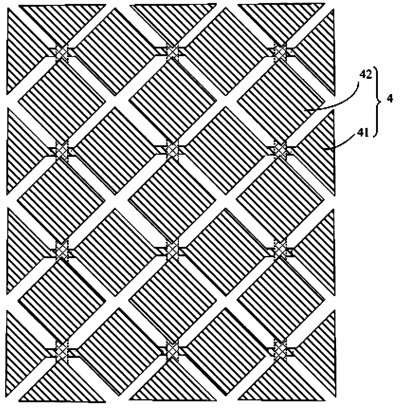
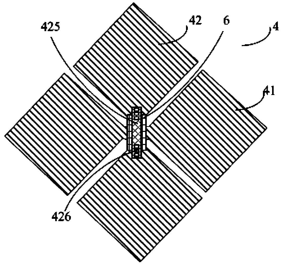
[0058] Such as Figure 5-7 As shown, the capacitive touch screen includes a substrate and a sensor electrode 4 arranged on the substrate. The sensor electrode 4 includes a first electrode group 41 arranged in parallel in multiple rows and a second electrode group 42 arranged in parallel in a plurality of columns. The first electrode group 41 includes A plurality of first electrodes 411 are electrically connected in sequence, and the second electrode group 42 includes a plurality of second electrodes 421 electrically connected in sequence. In this embodiment, both the first electrode 411 and the second electrode 421 include peripheral electrodes distributed around the periphery and a central electrode electrically isolated from the peripheral electrodes, and adjacent peripheral electrodes in the same row / column are electrically connected to each other.

[0059] Such as Figure 7 As shown, a closed first isolation trench 412 is opened in the first electrode 411. The inner side ...

Embodiment 2

[0102] The difference between this embodiment and Embodiment 1 is that, in the capacitive touch screen structure of this embodiment, the second conduction part is formed on the same layer as the first electrode and the second electrode, and the first conduction part is arranged on the second conduction part. Below the part, a via hole is provided in the insulating layer, and the first conducting part is electrically connected to the first electrode through the via hole.

[0103] In this embodiment, the first electrode, the second electrode and the second conducting part are formed by indium tin oxide; A material is formed.

[0104] Correspondingly, the preparation method specifically includes the following steps:

[0105] Step S11: forming a pattern including a first conducting portion on the substrate.

[0106] Step S12 : On the substrate after step S11 , an insulating layer is formed, and a via hole is opened in the insulating layer in a region corresponding to the end of ...

Embodiment 3

[0111] The difference between this embodiment and Embodiments 1 and 2 is that, in this embodiment, only the first electrode in the first electrode group, or only the second electrode in the second electrode group is provided with a closed isolation ditch groove.

[0112] Correspondingly, when forming the sensor electrodes in the manufacturing process, the mask used in the exposure process not only has patterns corresponding to the formation of the first electrode 411 and the second electrode 421, but also has patterns corresponding to the formation of the first isolation trench. The groove 412 (corresponding to the closed isolation trench opened in the first electrode); or, also has a pattern corresponding to the formation of the second isolation trench 422 (corresponding to the closed isolation trench opened in the second electrode). Wherein, the pattern corresponding to the formation of the first isolation trench 412 or the second isolation trench 422 is the photoresist comp...


PUM

PropertyMeasurementUnit
widthaaaaaaaaaa

Abstract

The invention belongs to the technical field of display and relates to a capacitive touch screen and a manufacturing method. The capacitive touch screen comprises a base plate and sensor electrodes, wherein the sensor electrodes are arranged on the base plate; each sensor electrode comprises multiple lines of first electrode sets arranged in parallel and multiple lines of second electrode sets arranged in parallel; each first electrode set comprises multiple first electrodes electrically connected in sequence; each second electrode set comprises multiple second electrodes electrically connected in sequence; each first electrode and / or each second electrode comprise / comprises peripheral electrodes and a central electrode, the peripheral electrodes are distributed on the periphery, and the central electrode is electrically isolated from the peripheral electrodes; the adjacent peripheral electrodes on the same line / column are mutually electrically connected. The capacitive touch screen and the manufacturing method have the following benefits: the coupling between the sensor electrodes of the capacitive touch screen and common electrodes is smaller, so that RC (resistor capacitor) load is reduced, the sensor electrodes are faster in charging, and the touch induction sensitivity of the capacitive touch screen is ensured.

Description

technical field [0001] The invention belongs to the field of display technology, and relates to a capacitive touch screen and a preparation method. Background technique [0002] Touch screen is the latest information input device at present. It can realize human-computer interaction simply, conveniently and naturally, and provide people with a brand-new method of multimedia human-computer interaction. The earth satisfies people's visual and tactile enjoyment. [0003] According to different working principles and transmission media, touch screens can be divided into resistive, capacitive, surface acoustic wave, and infrared types. Among them, capacitive touch screens are widely used because of their high accuracy and strong anti-interference ability. [0004] At the same time, in order to achieve thinner and lighter touch screens, there have been methods of integrating touch panel functions with liquid crystal panels, specifically including the "In-cell" method and the "On-...

Claims


Application Information

Patent Timeline
Patent Type & Authority Applications(China)
IPC IPC(8): G06F3/044
CPCG02F1/13338G06F3/0445G06F3/0446G06F3/0448G06F2203/04103Y10T29/49105
Inventor 王静鲁友强
Owner BOE TECH GRP CO LTD
Why Eureka
Try Eureka