Wireless energy receiving coil and wireless energy transmission system

A technology for receiving coils and wireless energy, applied in electromagnetic wave systems, transformer/inductor coils/windings/connections, transformers, etc., can solve problems such as low energy transmission efficiency, improve energy transmission efficiency, improve energy transmission efficiency, improve Effects of using degrees of freedom

Inactive Publication Date: 2013-10-23
KUANG CHI INNOVATIVE TECH
View PDF9 Cites 3 Cited by
  • Summary
  • Abstract
  • Description
  • Claims
  • Application Information

AI Technical Summary

Problems solved by technology

[0005] The technical problem to be solved by the present invention is to overcome the shortcomings of low energy transmission efficiency of the existing resonant wireless energy transmission system, to provide a wireless energy receiving coil with higher system energy transmission efficiency and a wireless energy receiving coil with the wireless energy receiving coil. Transmission system

Method used


Image

  • Wireless energy receiving coil and wireless energy transmission system
  • Wireless energy receiving coil and wireless energy transmission system
  • Wireless energy receiving coil and wireless energy transmission system

Examples


Embodiment Construction

[0032] The present invention will be described in detail below in conjunction with the accompanying drawings.

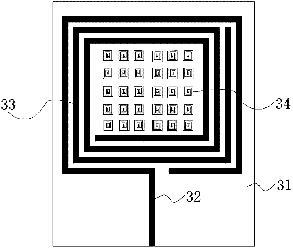
[0033] attached figure 1 It is a structural diagram of the wireless energy receiving coil 3, which consists of a base material 31 and a metal wire structure fixed on the base material 31. Its basic structure is similar to that of a PCB antenna. The base material can be an epoxy resin substrate, depending on the application Ceramic substrates can also be used on demand. The difference from PCB antennas is that the metal wire structure includes a feeder 32, a resonant metal coil 33, and a plurality of magnetic microstructures 34. The input end of the feeder 32 is connected to the signal input end of the receiving circuit. The feeder 32 Surrounding the resonant metal coil 33 is used to feed the received signal into the receiving circuit. A plurality of magnetic microstructures 34 are arranged in the central area of ​​the resonant metal coil 33. The magnetic microstructu...


PUM


Abstract

The invention provides a wireless energy receiving coil with higher system energy transmission efficiency and a wireless energy transmission system with the wireless energy receiving coil, aiming to overcome the defect that existing resonant wireless energy transmission systems are low in system energy transmission efficiency.

Description

【Technical field】 [0001] The invention relates to the field of wireless energy transmission, in particular to a wireless energy transmission system based on the principle of magnetic resonance. 【Background technique】 [0002] At present, wireless energy transmission technology is mainly based on three principles, namely electromagnetic induction, magnetic resonance and radiation. The basic feature of electromagnetic induction (non-contact inductive) power transmission circuit is the separation of primary and secondary circuits. There is a gap between it and the secondary circuit, which is connected by magnetic field coupling induction. The characteristics of the electromagnetic induction type are: there is a large air gap, so that the primary and secondary sides have no electrical contact, which makes up for the inherent defects of the traditional contact type electric energy; however, the existence of a large air gap also makes the magnetic flux leakage of the system compar...

Claims


Application Information

Patent Timeline
Patent Type & Authority Applications(China)
IPC IPC(8): H01F38/14H01F27/28H02J17/00H02J50/12
Inventor 刘若鹏栾琳郭洁洪运南
Owner KUANG CHI INNOVATIVE TECH
Why Eureka
Try Eureka