Waveguide power distribution synthesizer and power distribution and synthetic method

A synthesizer and waveguide technology, applied in the microwave field, can solve the problems affecting the synthesis efficiency of the synthesizer, the narrow space in the waveguide, and the limited number of stacked layers, etc., and achieve the effect of small and light structure, compact structure and improved isolation

Active Publication Date: 2013-10-23
CHINA ELECTRONIS TECH INSTR CO LTD
View PDF6 Cites 15 Cited by
  • Summary
  • Abstract
  • Description
  • Claims
  • Application Information

AI Technical Summary

Problems solved by technology

The advantage of this structure is that it is compact, but its biggest disadvantage is that the space in the waveguide is very narrow and the number of stacked layers is very limited in the millimeter wave frequency band. Therefore, this structure cannot achieve multi-channel power in the millimeter wave frequency band with higher frequencies. Allocation and Synthesis
In order to achieve multi-channel power distribution and synthesis, the coaxial-radial waveguide power division / combination scheme is generally adopted. The electromagnetic wave first enters the broadband radial waveguide from the coaxial, and then enters the rectangular waveguide from the radial waveguide to complete the power distribution and then enters the rectangular waveguide. Each signal enters the microstrip planar circuit through the rectangular waveguide-microstrip probe array conversion structure, and then completes the multi-channel power distribution and synthesis. However, this structure uses coaxial as the transmission medium for multi-channel power distribution and synthesis. The working frequency enters the 40GHz or even higher frequency band, and the coaxial is used as the transmission line, which has a large loss and will seriously affect the synthesis efficiency of the synthesizer

Method used


Image

  • Waveguide power distribution synthesizer and power distribution and synthetic method

Examples


Embodiment Construction

[0020] The following will clearly and completely describe the technical solutions in the embodiments of the present invention with reference to the accompanying drawings in the embodiments of the present invention. Obviously, the described embodiments are only some, not all, embodiments of the present invention. Based on the embodiments of the present invention, all other embodiments obtained by persons of ordinary skill in the art without making creative efforts belong to the protection scope of the present invention.

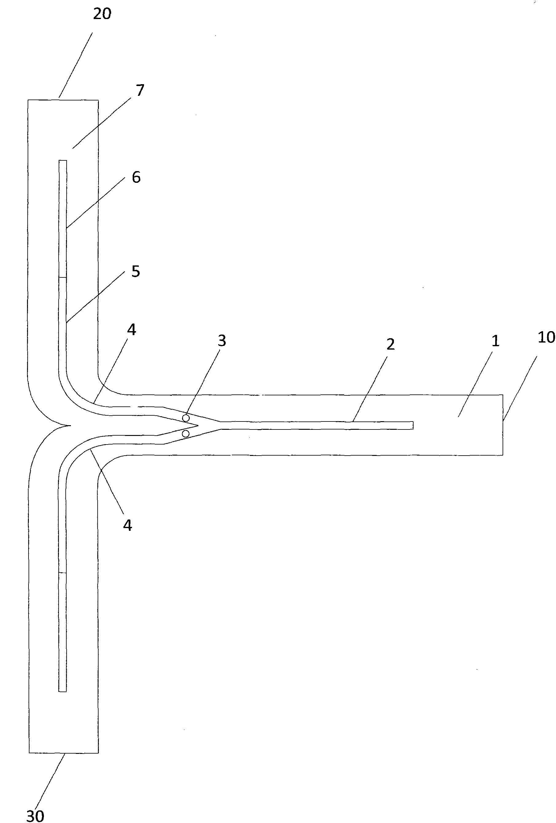
[0021] like figure 1 Shown, a kind of waveguide power distribution synthesizer comprises: first port 10, second port 20 and third port 30, the transmission path between the first port 10 to the second port 20 and the first port 10 to the third port The transmission paths between 30 are symmetrical, which are rectangular waveguide 1, tapered single-ridge waveguide 2, single-sided double-ridge waveguide 4, two-way ridge waveguide 5, tapered ridge waveguide 6, an...


PUM


Abstract

The invention provides a waveguide power distribution synthesizer which comprises a first port, a second port and a third port. The transmission path between the first port and the second port and the transmission path between the first port and the third port are symmetrical, the transmission path sequentially comprises a rectangular waveguide 1, a gradual change single ridge waveguide 2, single face double ridge waveguides 4, two path ridge waveguides 5, gradual change ridge waveguides 6 and rectangular waveguides 7, and distribution pillars 3 are symmetrically arranged in the single face double ridge waveguides 4. According to the waveguide power distribution synthesizer, the efficiency of the waveguide power distribution synthesizer is effectively improved, the stability of a high power amplifier designed based on the synthesizer is improved, and meanwhile the number of paths of the power distribution synthesizer based on the waveguides is increased.

Description

technical field [0001] The invention relates to the field of microwaves, in particular to a waveguide power distribution combiner, a power distribution method, and a power combination method. Background technique [0002] With the wide application of microwave and millimeter wave technology in the fields of radar, guidance and communication, higher and higher requirements are put forward for the bandwidth, output power and indicators of the millimeter wave signal source. Although the microwave and millimeter wave solid-state power amplifier chip has the advantages of small size, light weight, high reliability and compact circuit structure, the output power of a single solid-state device is affected by the physical characteristics of its own semiconductor and problems such as heat dissipation, processing technology, and impedance matching. However, it is far from the output power required in practical engineering, so it cannot meet the requirements of microwave and millimeter...

Claims


Application Information

Patent Timeline
Patent Type & Authority Applications(China)
IPC IPC(8): H01P5/16
Inventor 宁曰民
Owner CHINA ELECTRONIS TECH INSTR CO LTD
Why Eureka
Try Eureka