Fuel control method for fuel water heater

A technology of gas water heater and control method, which is applied to fluid heaters, lighting and heating equipment, etc., can solve the problems of affecting the combustion efficiency of the whole machine, wasting manpower and material costs, and cannot solve the difference of gas sources, etc., and achieves stable and comfortable use, The effect of reducing emissions and using environmental protection

Active Publication Date: 2013-10-30
HAIER GRP CORP +1
View PDF9 Cites 14 Cited by
  • Summary
  • Abstract
  • Description
  • Claims
  • Application Information

AI Technical Summary

Problems solved by technology

For example, the combustion calorific value reflected by the same natural gas in different regions is not the same. If one combustion parameter is used to work, it will definitely affect the combustion efficiency of the whole machine
[0004] In the prior art, constant temperature gas water heaters generally use dial switches and other similar methods to distinguish the gas sources in each region. Although this method can solve some of the gas source differences, it cannot solve all the gas source differences. This method wastes manpower and material resources

Method used


Image

  • Fuel control method for fuel water heater
  • Fuel control method for fuel water heater
  • Fuel control method for fuel water heater

Examples


Embodiment 1

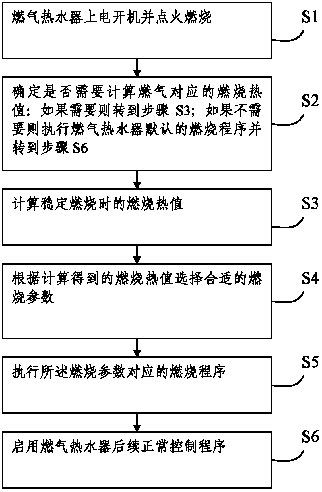
[0031] Such as figure 1 As shown, this embodiment records a gas water heater gas control method, including the following steps:

[0032] S1: The gas water heater is turned on and ignited;

[0033] S2: Determine whether it is necessary to calculate the combustion heat value corresponding to the gas: if necessary, go to step S3; if not, execute the default combustion program of the gas water heater and go to step S6;

[0034] S3: Calculate the combustion calorific value during stable combustion;

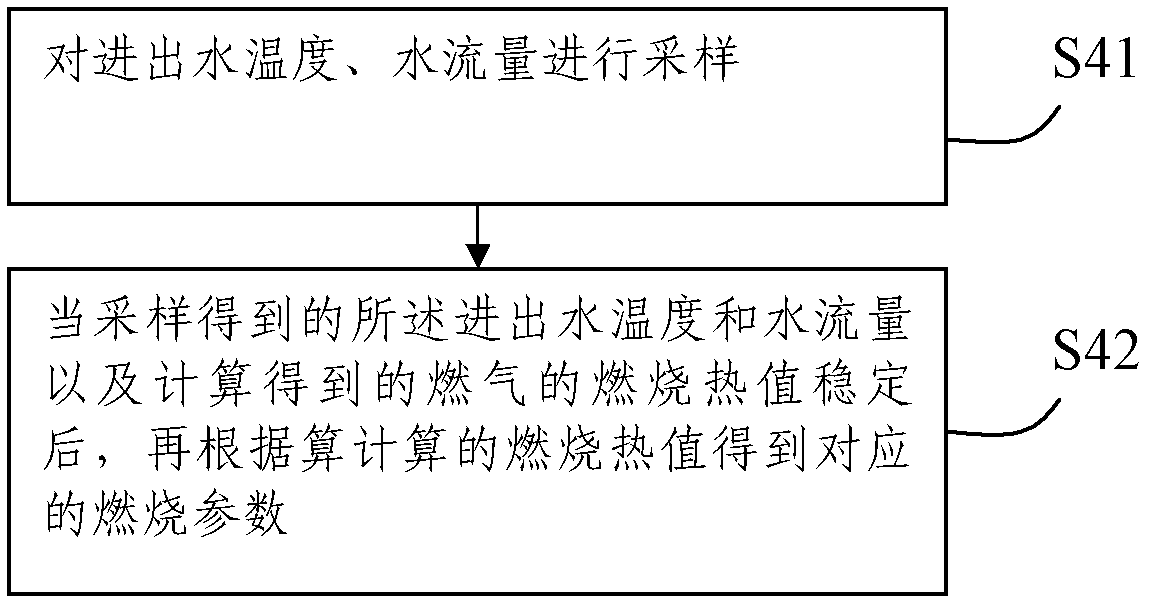
[0035] S4: Select appropriate combustion parameters according to the calculated combustion calorific value;

[0036] S5: Execute the combustion program corresponding to the combustion parameters;

[0037] S6: Enable the follow-up normal control program of the gas water heater.

[0038] Through step S2, the user can decide whether to distinguish the gas source, which makes the use more flexible. For example, the user may choose to select the combustion program only when using the g...

Embodiment 2

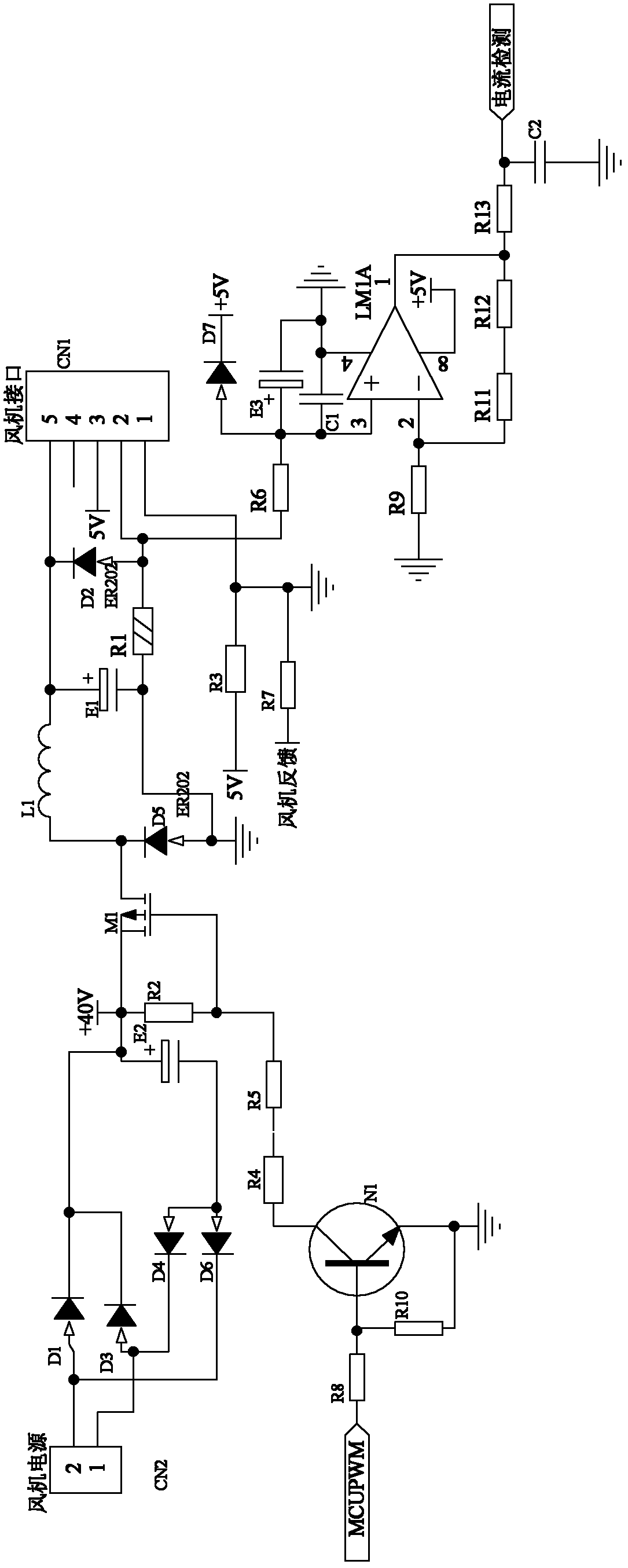
[0045] Such as image 3 Shown is a circuit that detects the current of the fan and controls the fan. The detection and control method is as follows: first, input the pwm (pulse width modulation) signal to the base of the triode N1 through the MCUPWM port, and control the switch of the triode N1; The voltage output by the fan power supply is controlled by the MOS tube M1 chopping to achieve the purpose of controlling the fan speed; the fan current is detected by a resistor R1, and then the signal is amplified by the operational amplifier LM1A and output to the current detection port of the MCU. According to the detected fan current The size of the fan and the size of the wind speed of the fan can determine the size of the external wind pressure, and then control the wind speed of the fan through the MCUPWM port to make up the wind to achieve the purpose of wind pressure resistance.

[0046] In the above control method, due to the influence of the fan itself and the temperature,...


PUM


Abstract

The invention discloses a fuel control method for a fuel water heater. The fuel control method includes the following steps: S1, powering on and starting up the fuel water heater and igniting for combustion; S2, determining whether calculation of a combustion heat value corresponding to fuel is needed or not, if yes, entering S3, and if not, executing a default combustion program of the fuel water heater and entering S6; S3, calculating a combustion heat value in stable combusting; S4, selecting a proper combustion parameter according to the combustion heat value; S5, executing the combustion program corresponding to the combustion parameter; S6, starting a subsequent normal control program of the fuel water heater. By the fuel control method, different kinds of gas sources of the fuel and difference, of the same kind of gas source, caused by areas or using time can be differentiated, and proper combustion parameters can be adopted correspondingly, so that the fuel can be combusted more fully.

Description

technical field [0001] The invention relates to the technical field of device control, in particular to a gas water heater gas control method. Background technique [0002] In the prior art, the "high energy efficiency" and "low-carbon environmental protection" of gas water heaters have increasingly become the focus of people's attention. In terms of environmental protection, waste emissions such as carbon monoxide and nitrogen oxides are required to be low, and the gas must be fully combustible. In addition, with the improvement of people's living standards, the requirements for the quality of bathing are getting higher and higher, which improves the stability, intelligence, constant temperature control, and comfort of gas water heater products when using water and gas. Require. [0003] At present, due to the differences in gas sources in various regions, it is necessary to distinguish the gas sources in each region in order to achieve full combustion of gas. Among them...

Claims


Application Information

Patent Timeline
Patent Type & Authority Applications(China)
IPC IPC(8): F24H9/20
Inventor 吴恩豪
Owner HAIER GRP CORP
Why Eureka
Try Eureka