Laser controller, laser control system and laser control method
A control system and controller technology, applied in the laser field, can solve the problem that the laser controller must manually switch the switch, etc., to achieve the effect of improving the control effect, improving the user experience, and reducing the complexity
- Summary
- Abstract
- Description
- Claims
- Application Information
AI Technical Summary
Problems solved by technology
Method used
Image


Examples
Embodiment 1
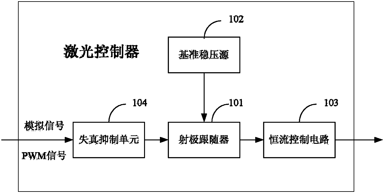
[0039] see figure 2 , the present embodiment provides a laser controller, including:
[0040] The emitter follower 101 is used to receive the modulation control signal, and output the modulation control signal after amplifying, the modulation control signal is an analog control signal or a PWM control signal;
[0041] A reference voltage source 102, used to provide voltage to the emitter follower 101;
[0042] The constant current control circuit 103 is used to output the driving current according to the modulation control signal output by the emitter follower 101, so as to control the working state of the laser diode;
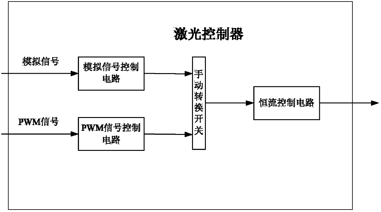
[0043] The function of the constant current control circuit is that if there is no external modulation control signal, the constant current control circuit will keep the current constant so that the laser diode remains on, which will not achieve the purpose of the laser show; apply the modulation control signal to the laser In scenes such as performances, t...
Embodiment 2
[0052] see Figure 4 , the present embodiment provides a laser control system, including: a laser controller 201, a computer control system 202 and a laser diode 203;
[0053] Wherein, the laser controller 201 includes:
[0054] The emitter follower is used to receive the modulation control signal, amplify the modulation control signal and output it, and the modulation control signal is an analog control signal or a pulse width modulation PWM control signal;
[0055] A reference voltage source for supplying voltage to the emitter follower;
[0056] A constant current control circuit, configured to output a driving current according to the state of the modulation control signal output by the emitter follower, so as to control the working state of the laser diode;
[0057] The reference stabilized voltage source is connected to an emitter follower, the output end of the emitter follower is connected to the input end of the constant current control circuit, and the output end o...
Embodiment 3
[0067] see Figure 5 , this embodiment provides a laser control method based on the laser controller provided in the above embodiments, including:
[0068] Step 301: The emitter follower receives the modulation control signal and amplifies the modulation control signal, wherein the modulation control signal is an analog control signal or a PWM control signal;
[0069] Step 302: The constant current control circuit outputs the driving current according to the state of the modulation control signal output by the emitter follower, so as to control the working state of the laser diode.
[0070] The method is executed by a laser controller, and the functions of the laser controller are the same as those described in the above embodiments, and will not be repeated here.
[0071] In this embodiment, further, in order to suppress the distortion of the analog control signal input to the emitter follower, the laser controller may also include a distortion suppression unit, and correspo...
PUM
 Abstract
Description
Claims
Application Information
 - R&D
- Intellectual Property
- Life Sciences
- Materials
- Tech Scout
- Unparalleled Data Quality
- Higher Quality Content
- 60% Fewer Hallucinations
Browse by: Latest US Patents, China's latest patents, Technical Efficacy Thesaurus, Application Domain, Technology Topic, Popular Technical Reports.
© 2025 PatSnap. All rights reserved.Legal|Privacy policy|Modern Slavery Act Transparency Statement|Sitemap|About US| Contact US: help@patsnap.com