
Construction method for embedding pipe in ground source heat pump pouring pile reinforcement cage

A technology of ground source heat pump and construction method, which is applied in heat pump, sheet pile wall, foundation structure engineering and other directions, can solve the problem of affecting the popularization and application of ground source heat pump technology of pile buried pipe, affecting the bearing capacity and durability of pile foundation, and increasing the reinforcement of steel bars. The risk of cage corrosion, etc., achieves the effect of significant heat transfer effect, easy quality control, and shortened construction period.

Active Publication Date: 2013-11-06
HOHAI UNIV
View PDF7 Cites 38 Cited by
  • Summary
  • Abstract
  • Description
  • Claims
  • Application Information

AI Technical Summary

Problems solved by technology

However, the embedding method of binding the heat transfer tubes on the steel cage in the cast-in-place pile not only affects the concrete volume in the cast-in-place pile, but also increases the risk of the steel cage being corroded, thus affecting the bearing capacity and durability of the pile foundation
It is these technical deficiencies and problems that affect the doubts of pile foundation design engineers about the use of pile-buried ground-source heat pump technology, and ultimately affect the popularization and application of pile-buried ground-source heat pump technology

Method used


Image

  • Construction method for embedding pipe in ground source heat pump pouring pile reinforcement cage
  • Construction method for embedding pipe in ground source heat pump pouring pile reinforcement cage
  • Construction method for embedding pipe in ground source heat pump pouring pile reinforcement cage

Examples


Embodiment Construction

[0034]The specific implementation manner of the patent of the present invention is described in detail below in conjunction with accompanying drawing. The protection scope of the patent of the present invention is not limited only to the description of this embodiment.

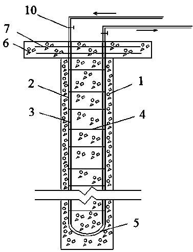
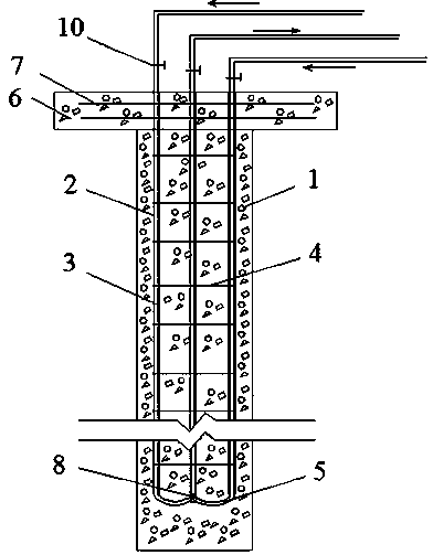
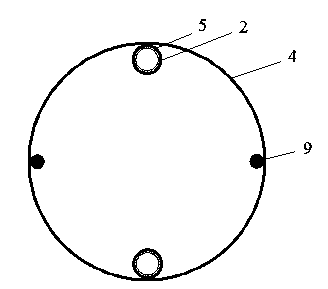
[0035] like Figure 1-Figure 5 As shown, a technical scheme of buried pipes in the steel cage of ground source heat pump cast-in-situ piles, the steel cage is composed of the steel pipe main reinforcement 2, the solid steel main reinforcement 9 and the stirrup 4, the steel pipe 2 is embedded with the heat transfer pipe 3, and the heat transfer pipe 3 It is connected by the bent joint 5 of the heat transfer pipe or by the tee pipe joint 8, the steel mesh 7 constructed by the pile cap is connected with the pipe main reinforcement 2 and the solid main reinforcement 9, the heat transfer pipe 3 is controlled by the set switch 10, and finally forms a reinforcement cage embedded Tube of concrete pile 1 and concrete ...


PUM

PropertyMeasurementUnit
Diameteraaaaaaaaaa
Pile lengthaaaaaaaaaa
Thicknessaaaaaaaaaa

Abstract

The invention discloses a construction method for embedding a pipe in a ground source heat pump pouring pile reinforcement cage. A steel pipe is used for substituting for a solid reinforcing steel bar as the main rib of a pouring pile reinforcement cage, and a heat transmission pipe is embedded in the steel pipe, as a result, problems caused by binding and embedding the heat transmission pipe and the reinforcement cage, including mutual interference, high probability of corrosion of a reinforcing steel bar, effect on overall bearing capacity of a pile foundation and the like, are solved. Compared with the traditional way of binding and embedding the heat transmission pipe and the reinforcement cage, the construction method is higher in survival rate of embedded pipe, compactedness of concrete is high, and embedment of the heat transmission pipe surely does not lower the overall bearing capacity of the pile foundation; compared with another traditional way of drilling and pipe embedding, the construction method greatly shortens construction period and saves underground space and engineering cost. The construction method is simple in construction process, strong in operability, convenient for quality control, and remarkable in economic benefit and heat transmission effect.

Description

[0001] technical field [0002] The invention relates to the technical field of pile buried pipes of ground source heat pump systems, in particular to a construction method for buried pipes in steel cages of ground source heat pump cast-in-situ piles. It is mainly applicable to the field of construction pile foundation and ground source heat pump technology. Background technique [0003] Ground source heat pump technology is a relatively stable temperature characteristic of underground soil, surface water, groundwater, etc., through the use of the earth as an energy storage body for heat exchange (store heat in the upper part of the ground in summer; transfer heat from the ground to the upper part in winter) The air-conditioning system of renewable energy in the building) replaces the traditional air-conditioning technology to achieve the purpose of energy saving and emission reduction. Buried heat exchangers underground is the construction difficulty and investment focus o...

Claims


Application Information

Patent Timeline
IPC IPC(8): F16L1/028E02D5/36F25B30/06
Inventor 孔纲强彭怀风吴宏伟丁选明
Owner HOHAI UNIV
Learn More