
Parallel optical emission assembly based on 45-degree fiber array and manufacturing method thereof

A technology of optical fiber array and optical transmission, which is applied in the coupling of electromagnetic transmitters and optical waveguides, can solve the problems that hinder the development and production of parallel optical transceiver modules, and achieve the effects of small thermal expansion coefficient, good high-frequency characteristics, and compact structure

Inactive Publication Date: 2013-11-06
WUHAN POWERISE OPTOELECTRONICSAL TECH
View PDF6 Cites 16 Cited by
  • Summary
  • Abstract
  • Description
  • Claims
  • Application Information

AI Technical Summary

Problems solved by technology

Parallel module manufacturers generally do not have this capability, thus hindering the development and production of parallel optical transceiver modules

Method used


Image

  • Parallel optical emission assembly based on 45-degree fiber array and manufacturing method thereof
  • Parallel optical emission assembly based on 45-degree fiber array and manufacturing method thereof
  • Parallel optical emission assembly based on 45-degree fiber array and manufacturing method thereof

Examples


Embodiment Construction

[0034] The principles and features of the present invention are described below in conjunction with the accompanying drawings, and the examples given are only used to explain the present invention, and are not intended to limit the scope of the present invention.

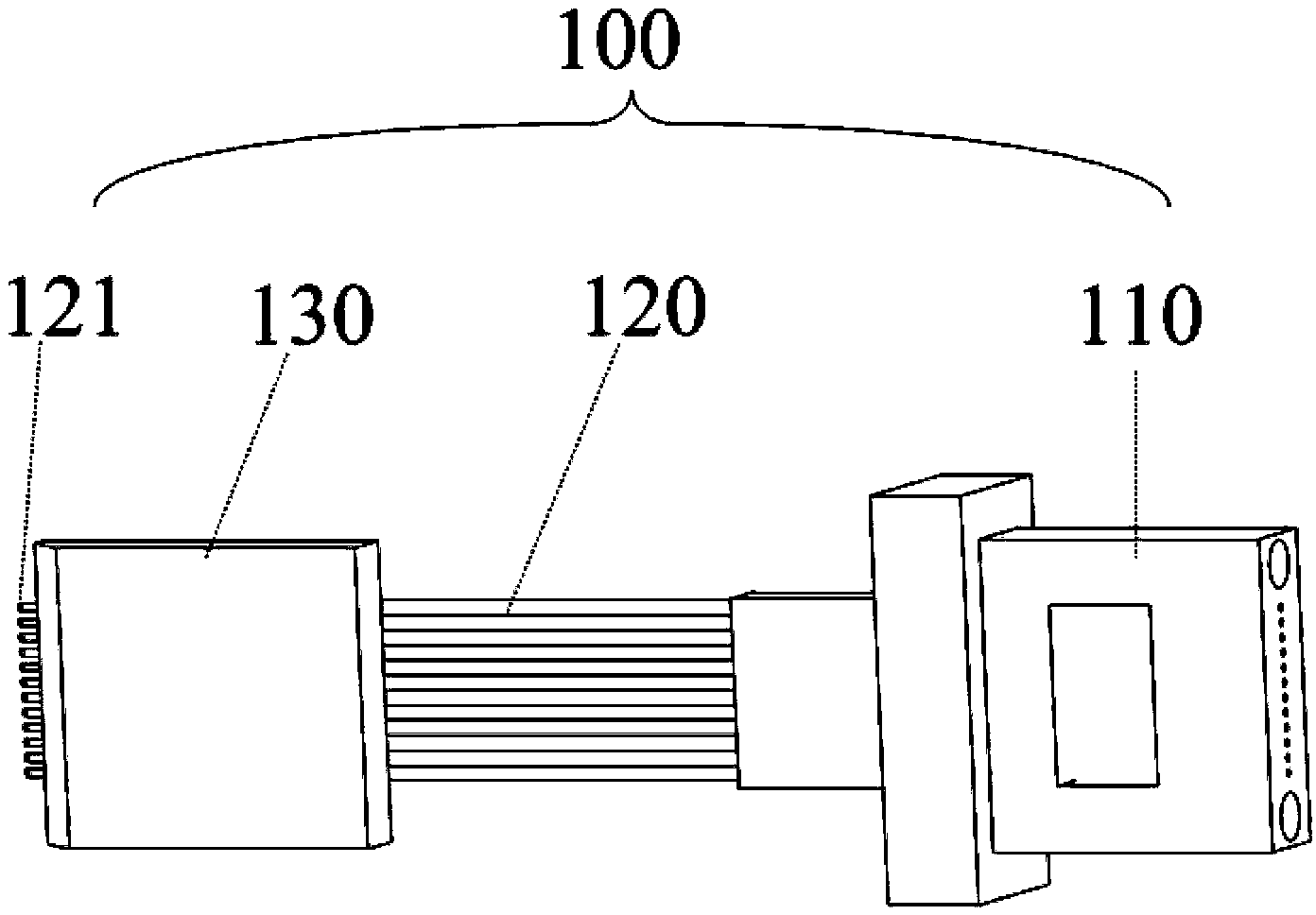
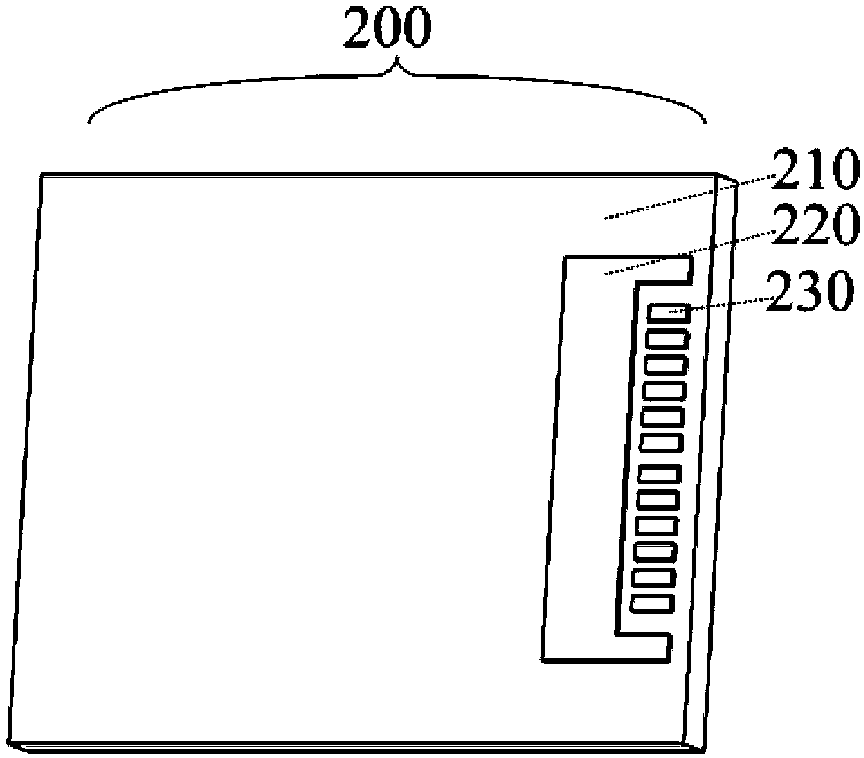
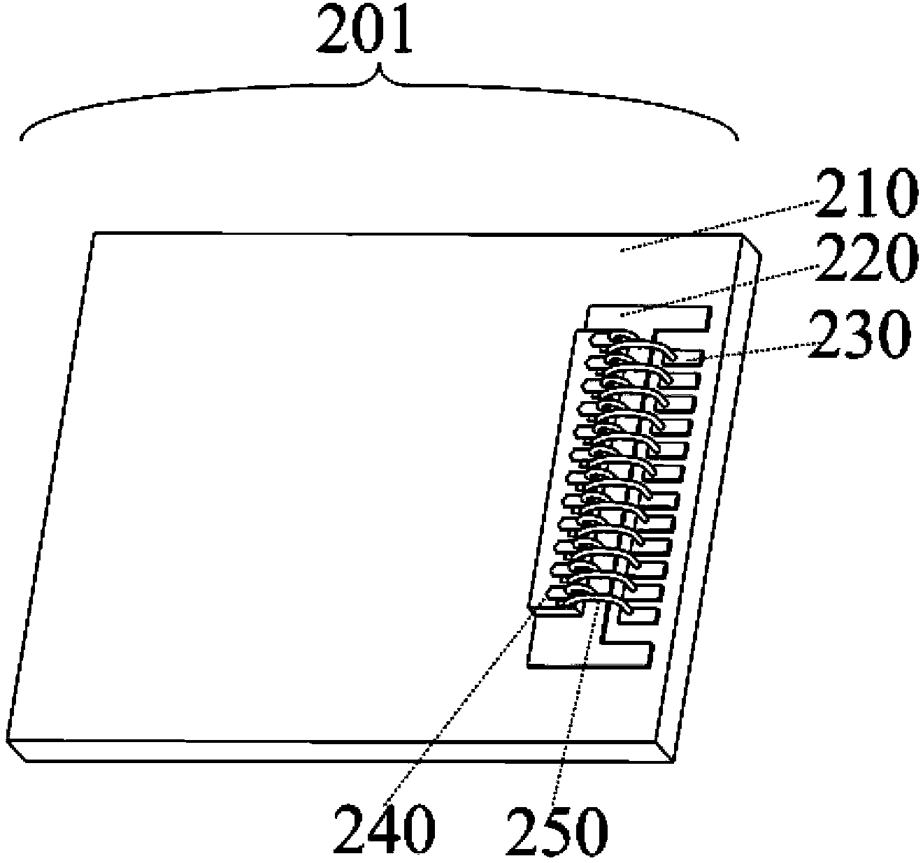
[0035] Such as figure 1 , figure 2 , image 3 , Figure 4 As shown, among them, Figure 4 It is a schematic structural view of an embodiment of a parallel optical launch assembly based on a 45° fiber array, figure 1 It is a schematic diagram of a 45° fiber array with an MT connector in a parallel optical launch assembly based on a 45° fiber array in the embodiment, figure 2 It is a schematic diagram of a ceramic substrate etched with electrodes and pads in a parallel optical emission component based on a 45° fiber array in the embodiment, image 3 It is a schematic diagram of a ceramic substrate bonded with a VCSEL laser array and bonded with gold wires in a parallel optical emission assembly based on a 45° f...


PUM


Abstract

The invention relates to a parallel optical emission assembly based on a 45-degree fiber array and a manufacturing method thereof. The parallel optical emission assembly comprises the 45-degree fiber array with an MT connector, a ceramic substrate and a VCSEL laser device array, wherein an electrode and a bonding pad are arranged on the ceramic substrate, the VCSEL laser device array is fixedly bonded on the electrode of the ceramic substrate, a bonding pad of a chip of the VCSEL laser device array is connected with the bonding pad of the ceramic substrate in a gold wire bonding mode, the 45-degree optical reflection surface of the 45-degree fiber array with the MT connector is in one-to-one aligned coupling with the VCSEL laser device array, and the 45-degree fiber array with the MT connector is fixed on the ceramic substrate. During usage, a user only needs to bond the ceramic substrate on a printed circuit board (PCB) of the user, driving signals of the VCSEL laser device array are connected with the bonding pad on the ceramic substrate in a routing mode, high-speed signals can demodulate and drive the VCSEL laser device array, parallel electric signals can be converted into parallel optical signals, and the parallel optical signals can be output to the standard MT connector through direct coupling of the 45-degree fiber array to be connected with the outside.

Description

technical field [0001] The invention relates to a parallel light emitting component and a manufacturing method thereof in the technical fields of parallel light transceiver modules and active optical cables in the optical communication technology. Background technique [0002] With the rapid growth of human's demand for communication, the existing communication system is facing greater challenges. Among them, speed and energy consumption are two very critical factors. People expect greater bandwidth in less space and lower power consumption. Therefore, the research on parallel optical transceiver modules has been extensively studied. [0003] Among commonly used communication lasers such as LD lasers and VCSEL lasers, VCSEL lasers have the advantages of high conversion efficiency and low threshold, so their power consumption is smaller than other types of lasers. The array is small and compact, and is very suitable for applications in the fields of parallel optical transm...

Claims


Application Information

Patent Timeline
Patent Type & Authority Applications(China)
IPC IPC(8): G02B6/42H04B10/50
Inventor 阮景江永胜罗志祥
Owner WUHAN POWERISE OPTOELECTRONICSAL TECH
Learn More