Pulping control circuit of cordless soybean milk machine

A cordless soya-bean milk machine and control circuit technology, which is applied in fields such as excitation or armature current control, dairy products, and beverage preparation devices, can solve problems such as complex structure, high instantaneous power of the motor, waste of industrial manufacturing costs, etc., and achieve simple control circuit , industrial manufacturing is simple, and satisfies the effect of portability

Active Publication Date: 2013-11-13
JOYOUNG CO LTD
View PDF4 Cites 4 Cited by
  • Summary
  • Abstract
  • Description
  • Claims
  • Application Information

AI Technical Summary

Problems solved by technology

In the above-mentioned electromagnetic heating soymilk machine, since the motor is arranged in the machine head and the electromagnetic heating coil is arranged in the cup body or the base, it is necessary to set two power cord plugs or take a plug between the machine head and the base to supply power to the motor and the electromagnetic heating coil. Connectors are required, which makes the wiring of the external power cord of the soymilk machine complicated, which is not conducive to consumers' demand for small and light home appliances. At the same time, the structure of multiple power plugs and connectors makes the cup body of the soymilk machine difficult. To solve the waterproof problem, there will be safety hazards
In addition, in order to achieve the working control of the electromagnetic heating coil, additional control circuits need to be installed in the cup body or the seat body, making the structure in the cup body complicated and the overall cost of the soybean milk machine rising.
[0004] Regardless of whether it is an electric heating tube or an electromagnetic heating soybean milk machine, when the grid voltage is too high, the instantaneous power and speed of the motor will exceed the rated value, and there is a hidden danger of the motor being burned due to the instantaneous power of the motor. The probability of waste increases, which brings costs to industrial manufacturing. Big waste

Method used


Image

  • Pulping control circuit of cordless soybean milk machine
  • Pulping control circuit of cordless soybean milk machine
  • Pulping control circuit of cordless soybean milk machine

Examples


Embodiment 1

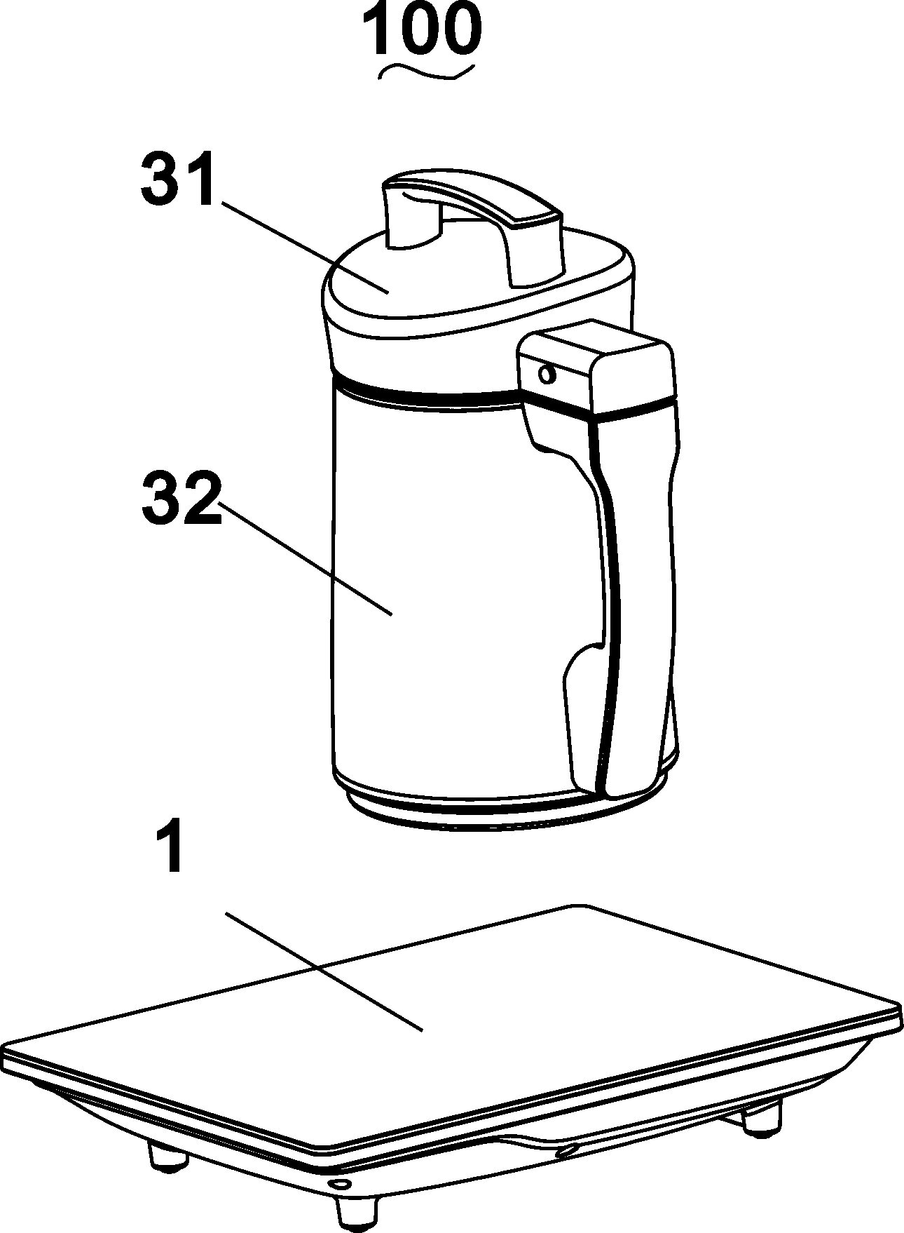
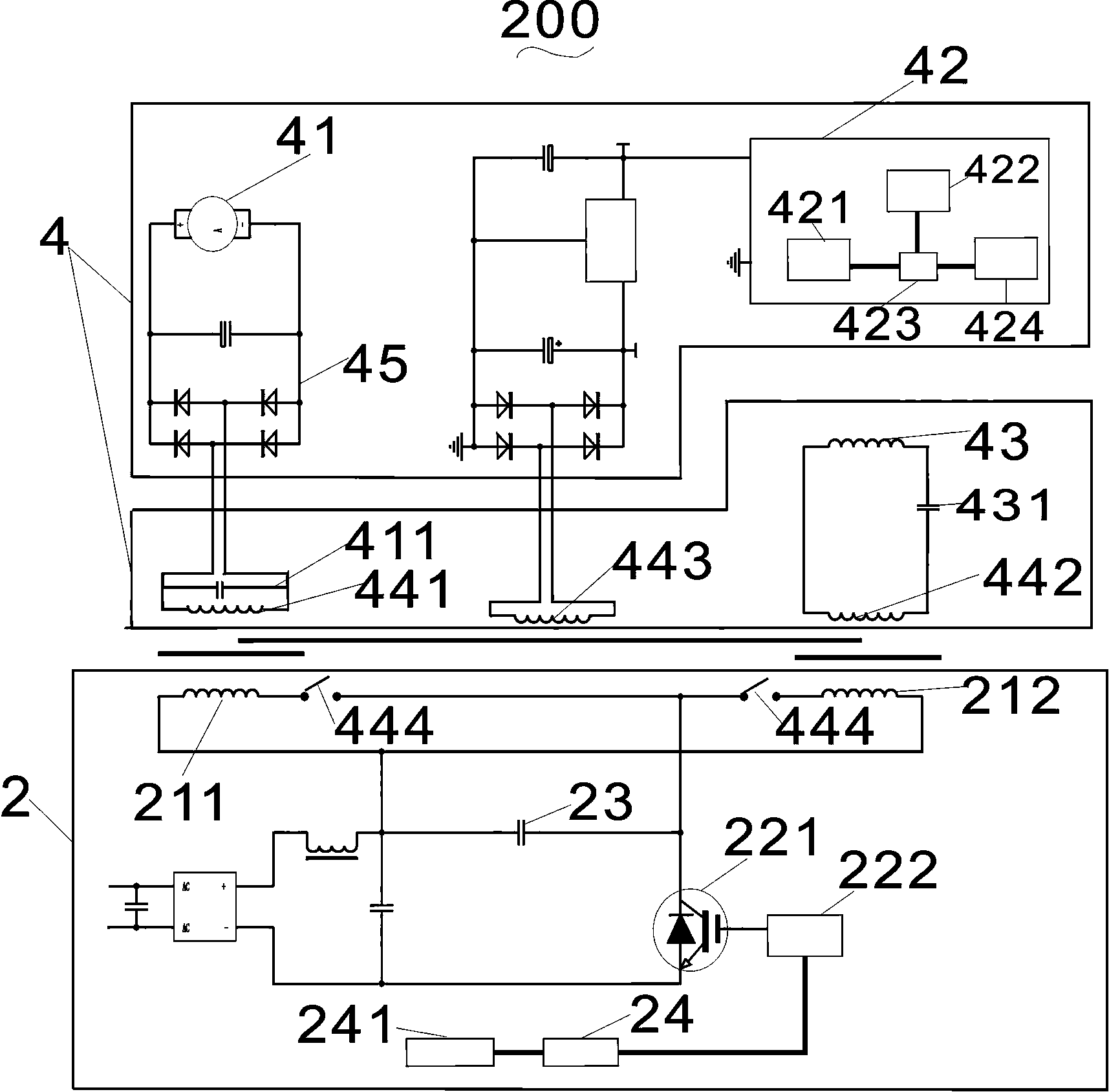
[0035] Such as Figure 1~2 Shown is the three-dimensional view of the cordless soybean milk machine 100 and the circuit diagram of the pulping control circuit 200 in the first embodiment of the invention. The machine body includes a machine head 31 and a cup body 32. On the cup body 32 , the motor 41 is connected to the magnetized winding 44 through an electromagnetic coupler. The electromagnetic coupler includes an upper coupler and a lower coupler, the upper coupler is connected with the motor 41 , and the lower coupler is connected with the magnetized winding 44 . The cup body 32 of the soymilk maker of the present invention does not need to separately install a power cord plug, which reduces safety hazards such as electric leakage and machine burn-in. At the same time, the electromagnetic heating coil 44 in the cup body 32 of the soymilk maker has a low calorific value and does not need additional ventilation and heat dissipation holes. The overall water resistance is bet...

Embodiment 2

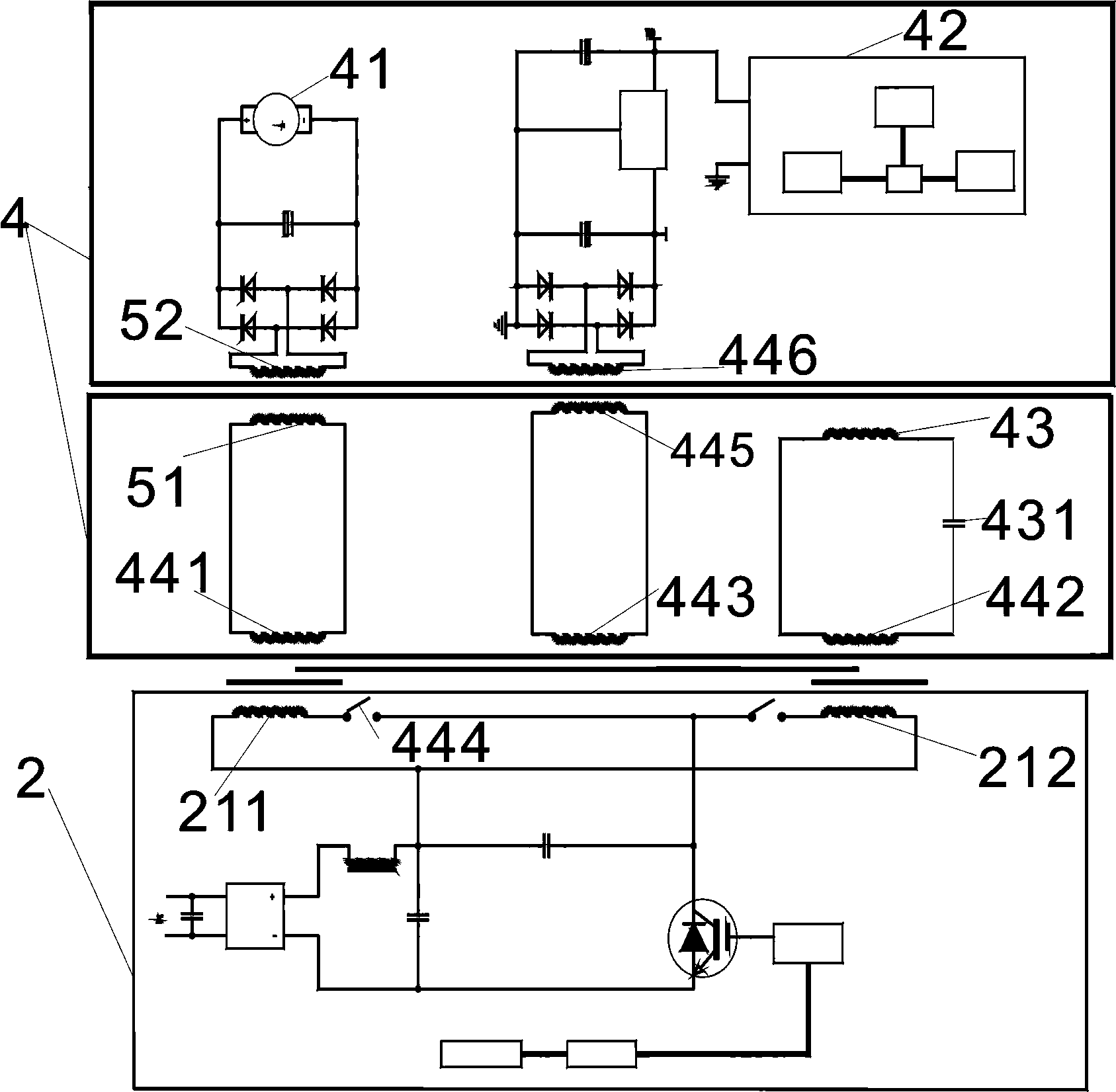
[0043] Such as image 3 Shown, its difference with embodiment one is:

[0044] The lower coupler is provided with a motor energy transmission coil 51 connected to the first coupling coil 441, the motor energy transmission coil 51 is installed in the cup body 32, and the upper coupler is provided with a motor secondary coupling coil 52 for supplying power to the motor 41. The motor secondary coupling coil 52 is coupled with the motor energy transmission coil 51 to obtain electric energy.

[0045] The aforementioned second coupling coil 442 is connected in series with the power supply energy transmission coil 445, the power supply energy transmission coil 445 is arranged in the cup body 32, and the second power supply energy transmission coil 446 coupled with the power supply energy transmission coil 445 is arranged in the handpiece 31. The two power supply energy transfer coils 446 are connected to the signal detection module 42 and supply power thereto. In this embodiment, b...

Embodiment 3

[0047] Such as Figure 4 Shown, its difference with embodiment two is:

[0048] The road of execution comprises motor voltage detection circuit 46, and motor voltage detection circuit 46 is arranged in the head 31, and motor 41 motor voltage detection circuit 46 is set in the head 31, and motor voltage detection circuit 46 is connected with signal detection module 42, and passes signal The detection module 42 transmits the motor signal to the controller 24 in the base body 1 , and the motor voltage detection circuit 46 can control the motor switch 461 to close to control the operation of the motor 41 .

[0049] The exciting winding 21 is an integral coil, and the corresponding magnetizing winding 44 is an integral coil. The electromagnetic heating coil 43 is connected with the magnetizing winding 44 and used for electromagnetic heating. The electromagnetic heating coil 43 is connected with the heating control switch 432. There is a central control module 47 for controlling th...


PUM


Abstract

The invention relates to a pulping control circuit of a cordless soybean milk machine. The pulping control circuit comprises a control branch arranged in a seat and an execution branch arranged in a machine body, and the execution branch comprises a motor, a signal detection module and an electromagnetic heating coil; and the control branch comprises an excitation winding, a resonant control module, a resonant capacitor and a controller, the resonant control module comprises IGBT and an IGBT driving loop, the excitation winding and the resonant capacitor are connected to form a high frequency resonant loop which outwardly outputs high frequency electric energy, the controller, the resonant control module and the high frequency resonant loop are sequentially electrically connected, the execution branch also comprises a magnetized winding corresponding to the excitation winding, the magnetized winding and the excitation winding are electromagnetically coupled to obtain electric energy, and the magnetized winding and the electromagnetic heating coil are electrically connected to provide electric energy required by the execution of crushing and boiling. The starting electric energy of the motor can be obtained without additionally connecting to a power plug, so a power line plug is no longer individually arranged in the cup of the soybean milk machine, thereby the hidden safety troubles comprising electric leakage, machine burning and the like are reduced.

Description

technical field [0001] The invention relates to the field of household appliances, in particular to a pulping control circuit of a cordless soybean milk machine. Background technique [0002] Soymilk machines in the prior art usually include a cup body, a machine head fastened on the cup body, a crushing device and a heating device, and the crushing device includes a motor and a crushing cutter. The crushing cutter is connected to the motor shaft of the motor and is controlled by the motor. To pulverize food for pulping. The heating device generally adopts the method of immersion electric heating tube heating or chassis electric heating tube heating. If the electric heating tube is used for heating, the electric heating tube needs to extend into the cup body, which will bring inconvenience to cleaning. It is easy to cause the problem of sticky bottom. [0003] In order to solve the above-mentioned problems caused by the existing heating methods of soybean milk machines, el...

Claims


Application Information

Patent Timeline
Patent Type & Authority Applications(China)
IPC IPC(8): A23C11/10A47J31/00A47J31/44A47J31/56H02P7/28
Inventor 朱泽春管兴勇王忠乔中义
Owner JOYOUNG CO LTD
Why Eureka
Try Eureka