
Satellite-borne multi-beam receiving antenna correction system and method

A technology of receiving antennas and correction systems, applied in diversity/multi-antenna systems, radio transmission systems, transmission systems, etc., can solve the problem that the algorithm cannot meet the requirements of real-time, increase the system complexity and correction cost, and increase the computing resources on the satellite. Speed ​​limitation and other issues can reduce the complexity of implementation, shorten the development cycle, and improve the radiation resistance performance.

Active Publication Date: 2013-11-13
SHANGHAI INST OF MICROSYSTEM & INFORMATION TECH CHINESE ACAD OF SCI +1
View PDF5 Cites 21 Cited by
  • Summary
  • Abstract
  • Description
  • Claims
  • Application Information

AI Technical Summary

Problems solved by technology

[0004] At present, there are many calibration methods for ground phased array antennas, but due to the limited computing resources and speed on the satellite, many of these algorithms cannot meet the real-time requirements
Especially when the number of channels increases, the resources required by the algorithm increase sharply
However, some active correction methods usually require a far-field signal source or a near-field probe antenna to correct the inconsistency of the array element, which increases the complexity of the system and the cost of correction.

Method used


Image

  • Satellite-borne multi-beam receiving antenna correction system and method
  • Satellite-borne multi-beam receiving antenna correction system and method
  • Satellite-borne multi-beam receiving antenna correction system and method

Examples


Embodiment Construction

[0028] The spaceborne multi-beam receiving antenna calibration system and calibration method thereof provided by the present invention will be described in detail below in conjunction with the accompanying drawings.

[0029] Firstly, a specific implementation of the satellite-borne multi-beam receiving antenna calibration system according to the present invention is given in conjunction with the accompanying drawings.

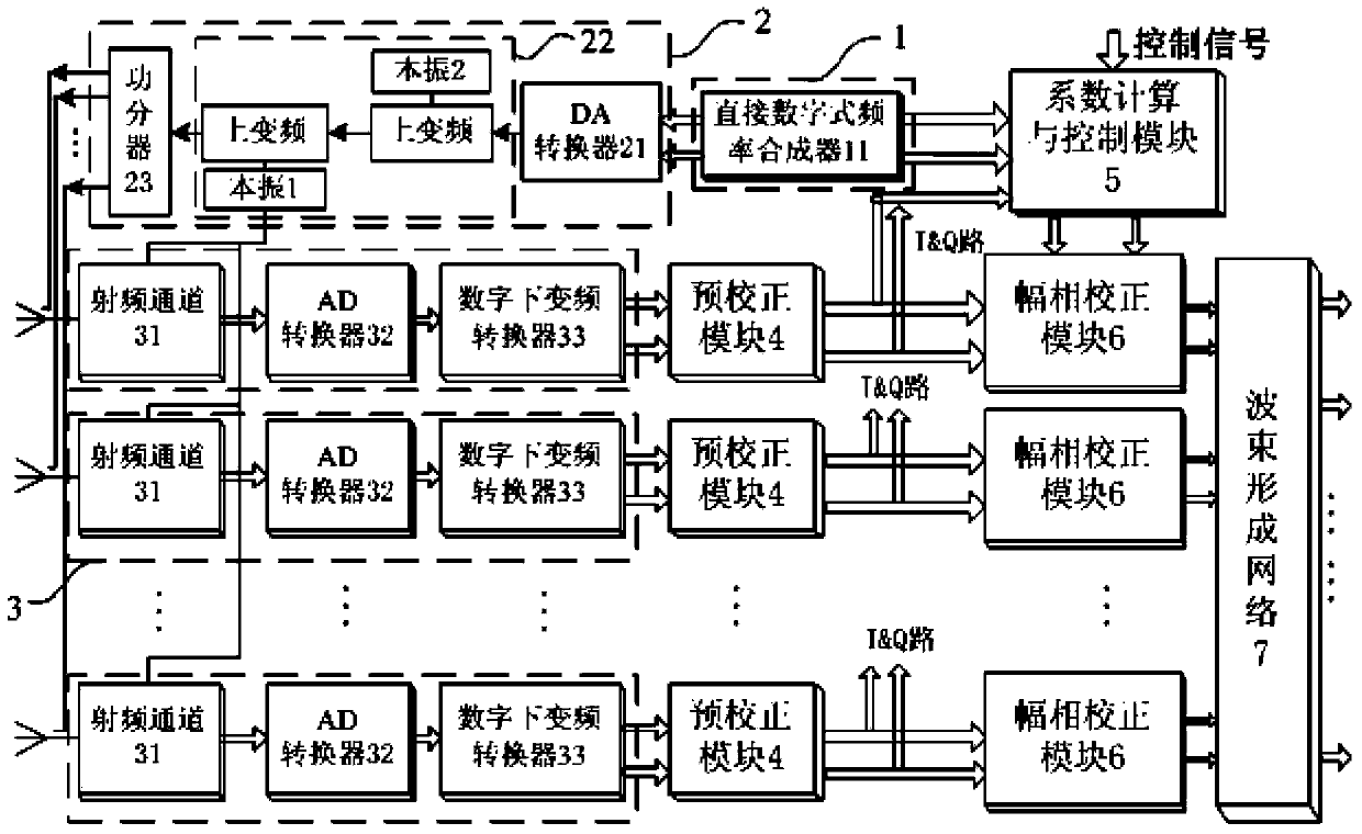
[0030] refer to figure 1 , a schematic diagram of the architecture of the spaceborne multi-beam receiving antenna calibration system of the present invention, the system includes a reference signal generation module 1, a reference signal up-conversion and power division module 2, a plurality of radio frequency down-conversion channels and a digital down-conversion module 3 , a plurality of pre-correction modules 4, a coefficient calculation and control module 5, and a plurality of amplitude and phase correction modules 6.

[0031] The reference signal generati...


PUM


Abstract

The invention discloses a satellite-borne multi-beam receiving antenna correction system and method. A reference signal generation module is used for generating orthogonal reference signals of two channels, namely, a channel I and a channel Q; reference signal up-converters and a power splitting module receive the reference signals and perform DA conversion; after the up-converters reach the antenna array element working frequency and are divided into multichannel signals, and the multichannel signals are sent to the front ends of radio frequency down converters of all the channels, so that the coupling from the reference signals to the radio frequency channels is completed; each radio frequency down-conversion channel and a digital down-conversion module perform down conversion and AD conversion on signals coupled to the radio frequency channels, and the signals are subjected to digital down conversion to an intermediate frequency band in a digital area and transmitted to precorrection modules; each precorrection module outputs corresponding corrected inconsistent precorrection signals among the channels; a coefficient calculation and control module controls all channels to calculate ampliphase coefficients according to the reference signals and the precorrection signals and transmits the corrected ampliphase coefficients to a corresponding ampliphase correction module; and the ampliphase correction module is used for completing correction of inconsistency of channel ampliphases according to the precorrection signals and the corresponding ampliphase coefficients.

Description

technical field [0001] The invention relates to the technical field of electronic communication, in particular to a novel space-borne multi-beam receiving antenna correction system and a correction method capable of performing amplitude-phase consistency correction on channels. Background technique [0002] The ever-increasing demand for global mobile communications has resulted in the increasingly tight spectrum resources and the increasingly saturated communication capacity of existing equipment, so new and efficient communication methods and technologies are urgently needed. Satellite mobile communication system, as an important supplementary form of global communication, has always been valued by people. In order to improve equipment communication capacity and suppress interference, many satellites now use digital multi-beam forming (DBF) technology. The digital multi-beam antenna can flexibly form various beam-forming, not only can effectively suppress noise, improve t...

Claims


Application Information

Patent Timeline
IPC IPC(8): H04B7/04H04B7/185
Inventor 王勇勇梁广余金培宋海伟
Owner SHANGHAI INST OF MICROSYSTEM & INFORMATION TECH CHINESE ACAD OF SCI
Learn More