
Printed circuit board arrangement for millimeter wave scanners

A technology of printed circuit boards and substrates, which is applied in the direction of printed circuits, circuit devices, printed circuit components, etc., can solve the problems of expensive structure of printed circuit board devices, achieve effective heat dissipation, reduce manufacturing costs, and improve measurement accuracy.

Active Publication Date: 2013-11-13
ROHDE & SCHWARZ GMBH & CO KG
View PDF8 Cites 13 Cited by
  • Summary
  • Abstract
  • Description
  • Claims
  • Application Information

AI Technical Summary

Problems solved by technology

[0004] EP 2 144 329 A1 has the disadvantage that the printed circuit board arrangement comprises a special substrate for the highest frequencies, which makes the construction of the printed circuit board arrangement expensive

Method used


Image

  • Printed circuit board arrangement for millimeter wave scanners
  • Printed circuit board arrangement for millimeter wave scanners
  • Printed circuit board arrangement for millimeter wave scanners

Examples


Embodiment approach

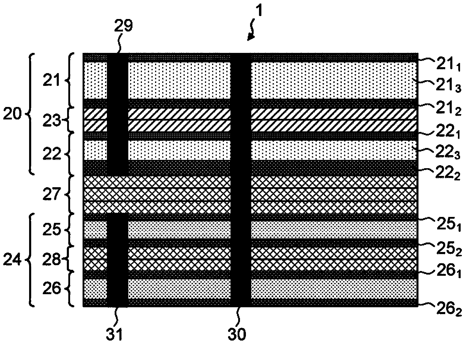
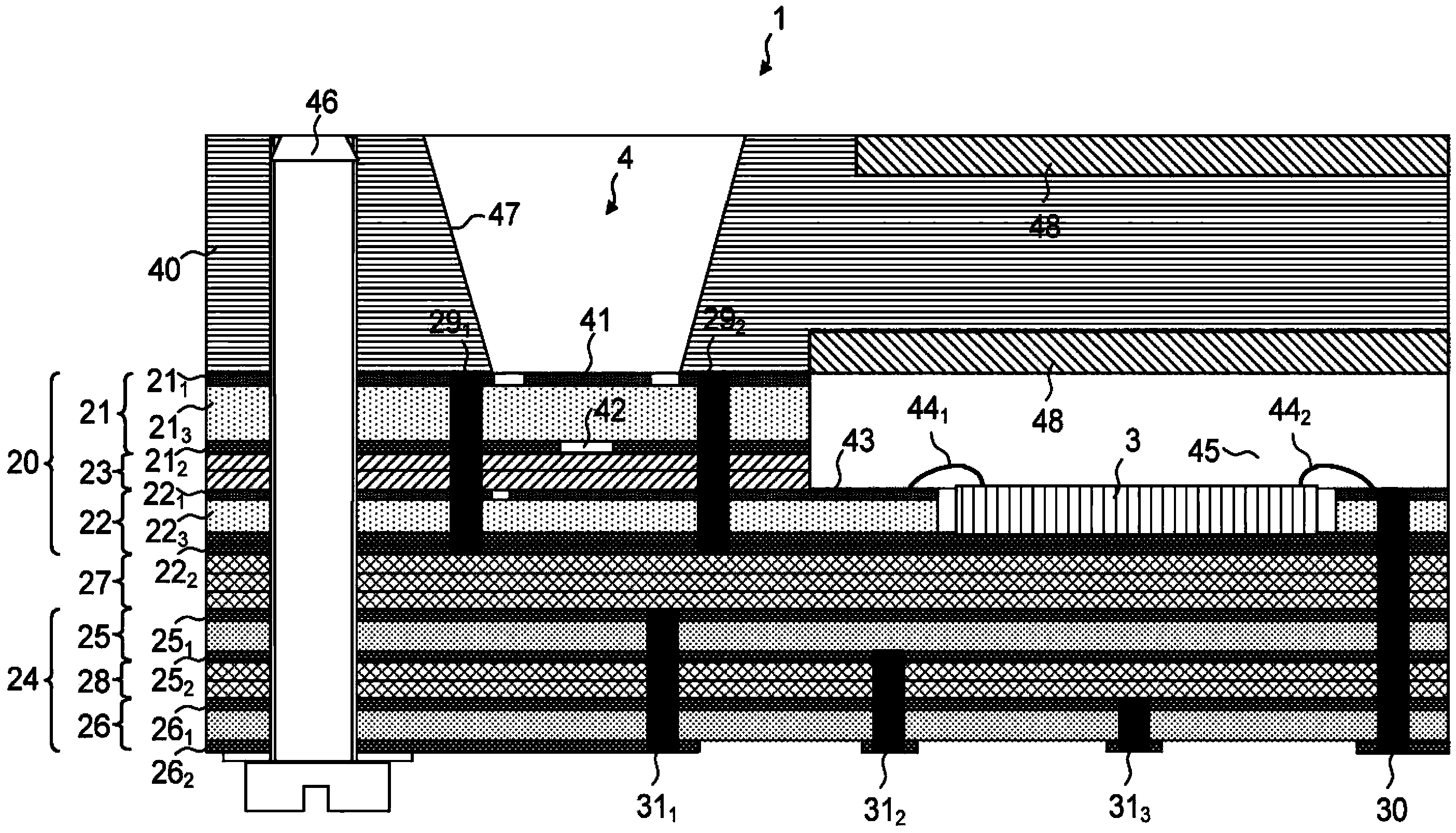
[0038] image 3 An exemplary embodiment of a section of a printed circuit board arrangement 1 according to the invention is shown, which comprises at least one antenna element 4 , a transmitting unit and / or receiving unit 3 and a cover 40 . image 3 The basic structure of the printed circuit board assembly 1 basically corresponds to figure 2 The structure of the printed circuit board assembly 1. exist image 3 Among them, the printed circuit board assembly 1 also includes a first part 20 and a second part 24, wherein the first part 20 and the second part 24 also include two printed circuit boards 21 and 22 and two printed circuit boards 25 and 26, respectively. exist image 3 Among them, the printed circuit board 21 and printed circuit board 22 of the first part 20 are also suitable for high frequency, while the printed circuit board 25 and printed circuit board 26 of the second part 24 are suitable for low frequency but not high frequency. The printed circuit board arran...


PUM


Abstract

A printed circuit board arrangement (1) electrically connects the at least one transmission and / or reception unit (3) to at least one antenna element (4), wherein the at least one transmission and / or reception unit (3) and the at least one antenna element (4) are integrated at least partially in the printed circuit board arrangement (1). The printed circuit board arrangement (1) comprises various printed circuit boards (21, 22, 25, 26), which are connected fixedly mechanically to one another. A first part (20) of the printed circuit board arrangement (1) is formed by at least one printed circuit board (21, 22), the substrate (213,223) of said printed circuit board consisting of a first material which is suitable for high frequencies, and a second part (24) of the printed circuit board arrangement (1) is formed by at least one printed circuit board (25, 26), the substrate of which consists of a second material, which is different than the first material and which is still sufficiently well suited for a low frequency and / or for a DC voltage range.

Description

technical field [0001] The invention relates to a printed circuit board arrangement having at least one partially integrated transmitting unit and / or receiving unit and at least one antenna element, which preferably operates in the millimeter wave frequency range. Background technique [0002] A printed circuit board arrangement capable of being used in a given environment for establishing electrical contact between the various transmitting units and / or receiving units and the corresponding antenna elements, wherein at the same time it shall be ensured for the corresponding transmitting unit and / or receiving unit power supply. In this context, the printed circuit board assembly should be designed in such a way that the structure of the entire system can be as compact as possible and the emission of unwanted interfering radiation is reduced to a minimum, wherein at the same time it must be ensured that the assembly as a whole has no interference with regard to electromagnetic...

Claims


Application Information

Patent Timeline
Patent Type & Authority Applications(China)
IPC IPC(8): H01Q1/38H01Q9/04H01Q21/06
CPCH01Q9/0407H01Q1/38H01Q21/065H01L23/66H01L2223/6627H01L2223/6677H01L2224/48091H01L2224/48227H01L2224/73265H01L2924/15153H01L2924/15313H01L2924/00014H05K1/0213H05K1/181
Inventor 拉尔夫·尤内曼克里斯蒂安·埃弗斯安德里亚斯·席塞尔谢里夫·艾哈迈德歌德·赫茨特夫茨勒
Owner ROHDE & SCHWARZ GMBH & CO KG
Learn More