

Continuous hot-drawing forming method for nickel-titanium alloy pipe
A hot-drawing and nickel-titanium alloy technology, applied in the field of continuous hot-drawing and forming of nickel-titanium alloy pipes, can solve the problems of ineffective control of dimensional tolerances, poor import channels, low process efficiency, etc., to avoid surface scratches , The effect of fast heating and good surface quality
- Summary
- Abstract
- Description
- Claims
- Application Information
AI Technical Summary
Problems solved by technology
Method used
Image

Examples
Embodiment 1
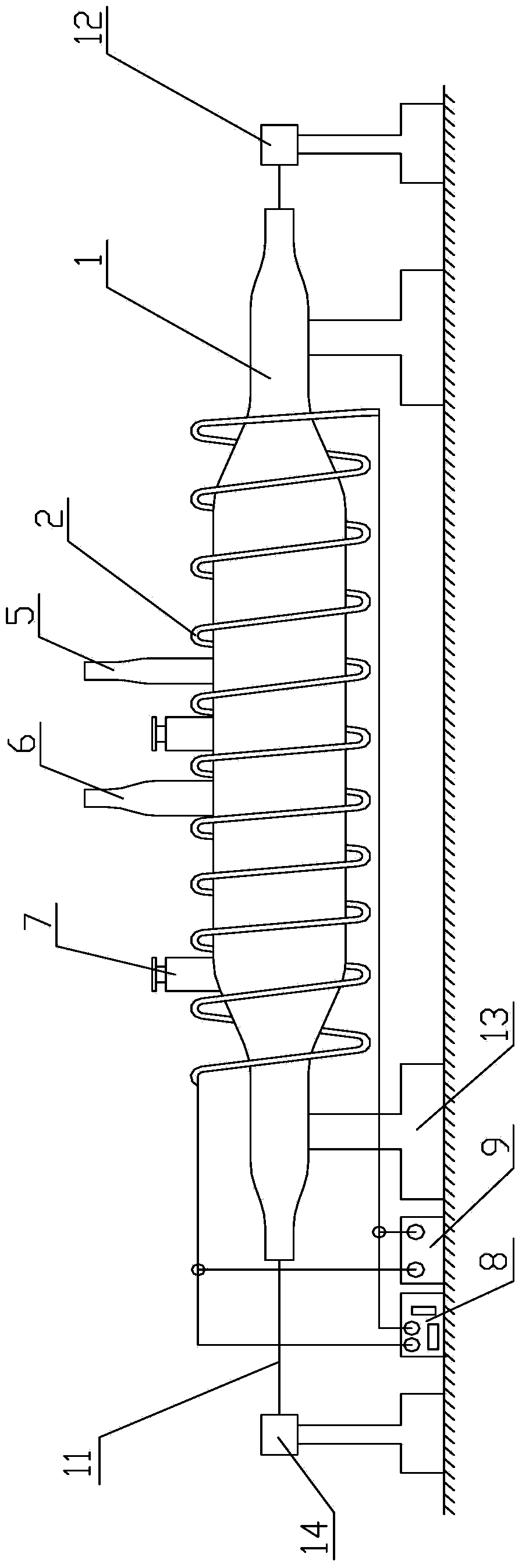
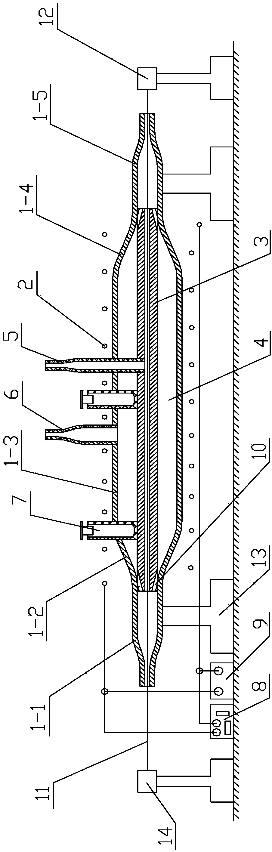
[0034] Such as figure 1 and figure 2 As shown, the continuous hot drawing device used in this embodiment includes a quartz tube 1, a graphite tube 3 arranged in the quartz tube 1, and an induction coil 2 wound outside the quartz tube 1, and is used to supply power to the induction coil 2 High-frequency induction heating power supply 8; the quartz tube 1 includes an inlet pipe 1-1, an equal-diameter section 1-3 connected to the inlet pipe 1-1 through a divergent section 1-2, and a tapered section 1-4 The outlet pipe 1-5 connected with the equal-diameter section 1-3; the left end of the graphite pipe 3 is attached to the inner wall of the right end of the inlet pipe 1-1, and the right end of the graphite pipe 3 is attached to the inner wall of the left end of the outlet pipe 1-5 Form a cavity 4 between the gradual expansion section 1-2 of the graphite tube 3 and the quartz tube 1, the equal diameter section 1-3 and the tapered section 1-4; the graphite tube 3 is provided with ...
Embodiment 2
[0043] The continuous hot drawing device used in this embodiment is the same as that in Embodiment 1.
[0044] The continuous hot drawing forming method of the present embodiment is:
[0045] Step 1. Insert a Φ6.5mm 316L stainless steel mandrel into a Ni-44Ti alloy tube blank with an outer diameter of 10mm and an inner diameter of 7mm to obtain an assembly 11; 500 mm of the tube blank is exposed; the roughness of the inner surface of the Ni-44Ti alloy tube blank is Ra<3.2, and the roughness of the outer surface of the mandrel is Ra<3.2; the surface of the mandrel is electroplated with a copper lubricating coating with a thickness of 10 μm;
[0046] Step 2. Insert the mandrel head of the assembly 11 from the inlet pipe 1-1, pass through the graphite tube 3 and exit from the outlet pipe 1-5, then pass through the drawing die of the drawing machine 12 and clamp On the fixture of the drawing machine 12, the mandrel afterbody of the assembly 11 is supported on the discharge rack 1...
Embodiment 3
[0050] The continuous hot drawing device used in this embodiment is the same as that in Embodiment 1.
[0051] The continuous hot drawing forming method of the present embodiment is:
[0052] Step 1. Insert a Φ6.5mm 316L stainless steel mandrel into a Ni-50.8Ti alloy tube blank with an outer diameter of 10mm and an inner diameter of 7mm to obtain an assembly 11; The tail is exposed to the tube blank by 200 mm; the roughness of the inner surface of the Ni-50.8Ti alloy tube blank is Ra<3.2, and the roughness of the outer surface of the mandrel is Ra<3.2; the surface of the mandrel is electroplated with a copper lubricating coating with a thickness of 2 μm ;
[0053] Step 2. Insert the mandrel head of the assembly 11 from the inlet pipe 1-1, pass through the graphite tube 3 and exit from the outlet pipe 1-5, then pass through the drawing die of the drawing machine 12 and clamp On the fixture of the drawing machine 12, the mandrel afterbody of the assembly 11 is supported on the...
PUM
| Property | Measurement | Unit |
|---|---|---|
| Thickness | aaaaa | aaaaa |
| Wall thickness | aaaaa | aaaaa |
| Wall thickness | aaaaa | aaaaa |
Abstract
Description
Claims
Application Information